Non-Contact Sampling for Explosive Trace Detection: Technologies, Applications, and Future Directions
This article provides a comprehensive overview of non-contact sampling methods for explosive trace detection, tailored for researchers, scientists, and security technology developers.
Non-Contact Sampling for Explosive Trace Detection: Technologies, Applications, and Future Directions
Abstract
This article provides a comprehensive overview of non-contact sampling methods for explosive trace detection, tailored for researchers, scientists, and security technology developers. It explores the fundamental principles and operational challenges of detecting ultra-low vapor pressure compounds. The scope ranges from foundational technologies like Ion Mobility Spectrometry (IMS) and Ambient Ionization Mass Spectrometry (AIMS) to advanced field applications and sensor optimization strategies. A thorough analysis of validation protocols and comparative performance between leading technologies such as SERS, GC-MS, and emerging core-sheath architectures is presented, offering a complete resource for professionals developing next-generation detection systems.
Principles and Challenges of Non-Contact Explosive Vapor Detection
The Critical Need for Non-Contact Sampling in Security and Defense
The detection of trace explosives is a critical component of modern security screening, yet conventional methods face significant operational limitations. Current standard practices predominantly rely on contact sampling (swabbing), where surfaces are physically wiped to collect microparticles that may contain explosive residues [1]. This approach presents inherent vulnerabilities, including variable sampling efficiency influenced by surface properties, particle types, and operator technique [1]. Perhaps most critically, surface sampling only collects from a small fraction of the total surface area, increasing the probability of missing residual traces of explosives [1].
Non-contact sampling methods represent a paradigm shift in security screening, potentially overcoming these limitations by permitting larger sampling areas, enabling direct passenger screening for vapor and particle sampling, and reducing costs per sample [1]. This application note examines the scientific basis, recent technological advances, and practical implementation protocols for non-contact sampling technologies within the broader context of explosive trace detectors (ETDs) research.
Technological Approaches to Non-Contact Detection
Vapor-Based Detection Systems
Explosive vapor detection has been recognized as an optimal method for standoff detection as it is inherently non-contact [1]. The primary scientific challenge lies in the extremely low vapor pressures of many target explosive compounds, which range from parts per trillion (pptv) to sub-parts per quadrillion (ppqv) [1]. Vapor dilution in air further complicates detection, often requiring sensitivity below the pptv level [1].
Recent advancements in atmospheric pressure ionization techniques coupled with mass spectrometry have enabled molecular detection of explosive vapors at these challenging concentration levels. Specifically, atmospheric flow tube-mass spectrometry (AFT-MS) and secondary electrospray ionization (SESI) have demonstrated the ability to detect explosive vapors at pptv to ppqv concentrations [1]. These technological developments now make feasible non-contact detection for practical security screening applications.
Spectroscopy-Based Techniques
Surface-Enhanced Raman Spectroscopy (SERS) has emerged as a powerful analytical technique for non-contact explosive detection. SERS achieves remarkable sensitivity, potentially enabling single-molecule detection through the use of noble metal substrates or structures [2]. This technique provides a distinct molecular "fingerprint" that can differentiate very similar compounds with high specificity, making it particularly valuable for identifying specific explosive compounds in complex environments [2].
Other spectroscopic methods showing promise include time-gated Raman spectroscopy, which utilizes a pulsed laser and an intensifier-charge coupled device (ICCD) synchronized with the optical pulse based on stand-off distance [2]. This approach is particularly well-suited for standoff detection scenarios where distance between the detector and potential threat is a operational requirement.
Quantitative Analysis of Non-Contact Detection Performance
Table 1: Comparative Analysis of Explosive Trace Detection Technologies
| Technology | Detection Principle | Standoff Distance | Key Explosives Detected | Sensitivity Level |
|---|---|---|---|---|
| AFT-MS with High-Volume Sampler | Vapor collection with mass spectrometry | Up to 2.5 meters [1] | RDX, Nitroglycerin [1] | Sub-pptv to ppqv [1] |
| SERS | Enhanced Raman scattering | Centimeter to meter scale [2] | Nitroaromatics, peroxide-based explosives [2] | Single-molecule detection potential [2] |
| Ion Mobility Spectrometry (IMS) | Gas phase ion separation at atmospheric pressure | Limited (typically requires proximity) [2] | TNT, RDX, PETN [2] | Nanogram to picogram [2] |
| GC-MS | Separation followed by mass analysis | Limited (typically requires collection) [2] | TNT, RDX, TATP [2] | Trace amounts (varies by compound) [2] |
Table 2: Market Analysis and Implementation Scope for ETD Systems
| Parameter | Current Market Value (2024) | Projected Market Value (2035) | Compound Annual Growth Rate (CAGR) | Leading Application Sectors |
|---|---|---|---|---|
| Global ETD Market | USD 6.92 Billion [3] | USD 12.96 Billion [3] | 6.48% (2025-2035) [3] | Aviation, Defense, Critical Infrastructure [3] |
| Regional Adoption | North America: Highest demand [3] | Asia Pacific: Fastest growth [3] | - | Transportation hubs, government facilities [3] |
Experimental Protocol: Standoff Vapor Detection Using AFT-MS
Principle and Scope
This protocol describes a methodology for standoff detection of explosive vapors at meter distances by combining Atmospheric Flow Tube-Mass Spectrometry (AFT-MS) with a high-volume air sampler, based on experimental work documented by Nims et al. [1]. The method leverages high-volume air collection to increase the effective distance for explosive vapor detection by overcoming natural air currents and vapor dilution effects.
Materials and Equipment
- Atmospheric Flow Tube-Mass Spectrometer (AFT-MS) system
- High-volume air sampler (flow rate: 225-240 L/min) [1]
- Explosive vapor standards (e.g., RDX, nitroglycerin)
- Saturated vapor source for calibration
- Laboratory space with controlled air currents (∼8m × ∼8m × ∼2.6m used in reference study) [1]
- Standard laboratory safety equipment
Procedure
System Calibration:
- Establish a saturated RDX vapor source within the testing environment.
- Position the AFT-MS system and connect the high-volume air sampler.
- Calibrate the mass spectrometer for target compounds using standard procedures.
Experimental Setup:
- Place the vapor source in a location with measurable air currents.
- Position the high-volume air sampler at predetermined distances from the vapor source (0.5m, 1m, 2.5m).
- Ensure the sampler is oriented to collect air from the direction of the vapor source.
Sample Collection:
- Activate the high-volume air sampler at its operational flow rate (225-240 L/min).
- Collect air samples for predetermined time intervals (typically 5-10 minutes).
- Direct the collected air samples into the AFT-MS for analysis.
Downstream and Upstream Testing:
- Perform comparative testing with the sampler positioned both downstream and upstream from the vapor source relative to room air currents.
- Record detection signals at each position to determine optimal placement.
Data Analysis:
- Monitor mass spectra for characteristic ions of target explosives (e.g., RDX at m/z 257.1083, 129.0656) [1].
- Compare signal intensities at different distances to establish detection limits.
- Evaluate the impact of room air currents on detection sensitivity.
Expected Results
When properly implemented, this protocol should demonstrate:
- Reliable vapor detection at distances up to 2.5 meters from a saturated RDX vapor source [1]
- Detection capability both downstream and upstream of the vapor source, with stronger signals typically observed in downstream positions [1]
- Signal intensity correlation with sampler positioning relative to room air currents
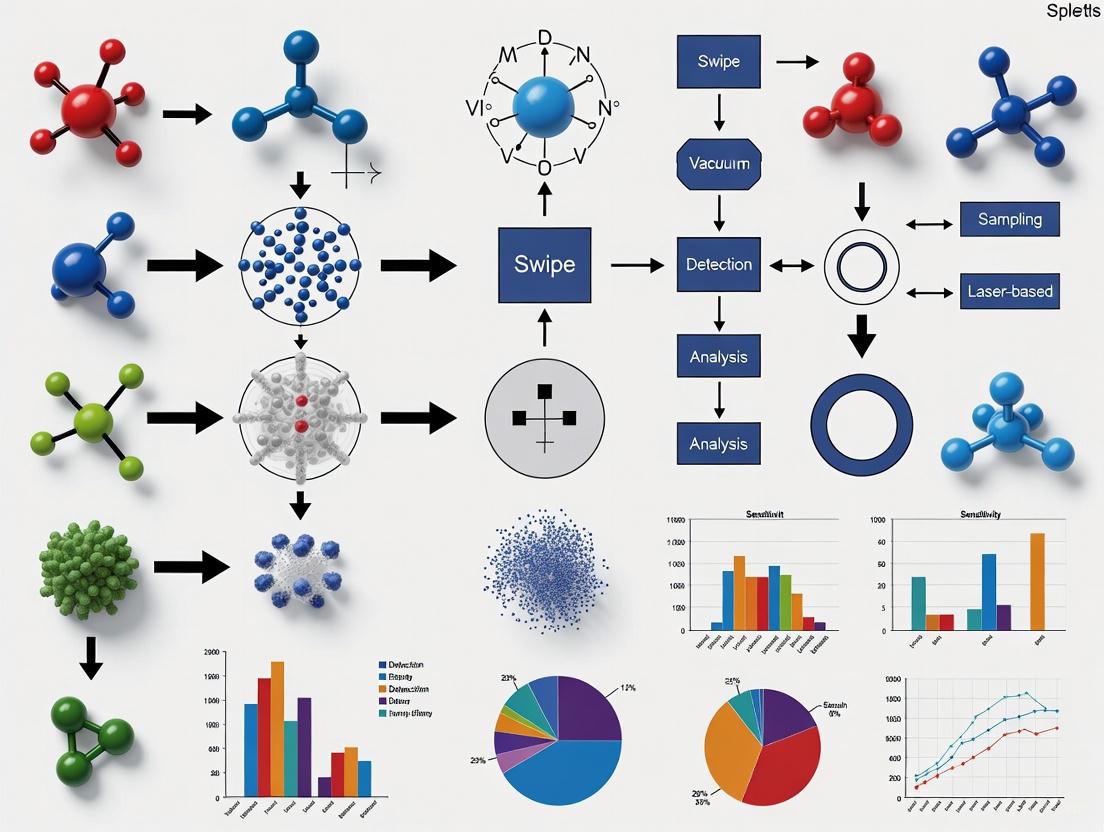
Workflow Visualization: High-Volume Air Sampling for Standoff Detection
Non-Contact Vapor Detection Workflow: This diagram illustrates the sequential process for standoff explosive vapor detection using high-volume air sampling coupled with AFT-MS analysis.
The Researcher's Toolkit: Essential Materials for Non-Contact ETD Research
Table 3: Essential Research Reagents and Equipment for Non-Contact ETD Development
| Item | Function/Application | Specific Examples/Properties |
|---|---|---|
| Atmospheric Flow Tube-Mass Spectrometer (AFT-MS) | Enables sensitive detection of explosive vapors at ultra-low concentrations [1] | Capable of detecting vapors at pptv to ppqv levels; used with high-volume air sampler [1] |
| High-Volume Air Sampler | Extends standoff detection distance by increasing sample volume [1] | Flow rate of 225-240 L/min; overcomes room air currents [1] |
| SERS Substrates | Enhances Raman signals for sensitive explosive detection [2] | Noble metal nanostructures (gold, silver); enable single-molecule detection potential [2] |
| Explosive Analytical Standards | System calibration and method validation [1] [2] | RDX, nitroglycerin, TNT, PETN; available as saturated vapor sources or residue [1] |
| Ambient Ionization Sources | Enable direct analysis of samples without complex preparation [2] | Desorption electrospray ionization (DESI), dielectric barrier discharge ionization (DBDI) [2] |
Non-contact sampling technologies represent a significant advancement in explosive trace detection, addressing critical limitations of conventional contact-based methods. The integration of high-volume air sampling with sensitive detection techniques like AFT-MS enables reliable vapor detection at practical standoff distances up to 2.5 meters [1]. Emerging technologies such as SERS and ambient ionization mass spectrometry further expand the capabilities for non-contact detection with increasingly superior sensitivity and specificity [2].
Future research directions should focus on miniaturization and portability of detection systems, integration of artificial intelligence and machine learning for improved detection accuracy and reduced false positives, and development of multi-modal detection systems that combine complementary technologies for enhanced reliability [3]. Additionally, ongoing research addresses challenges in detecting explosives with particularly low vapor pressures and those deliberately concealed to evade detection [1] [2].
As global security requirements continue to evolve, non-contact sampling technologies are poised to play an increasingly vital role in protecting transportation systems, critical infrastructure, and public spaces while enabling more efficient and less intrusive security screening protocols.
Vapor pressure is a fundamental physicochemical property defined as the pressure exerted by a vapor in thermodynamic equilibrium with its condensed phases (solid or liquid) at a given temperature. For trace detection, particularly of explosives and narcotics, the saturation vapor pressure of a compound determines its equilibrium partitioning between the condensed and gas phases, directly influencing the concentration of trace vapors available for non-contact sampling [4]. Accurate prediction and measurement of vapor pressure are therefore critical for determining the theoretical detectability of target compounds and for optimizing the performance of non-contact trace detectors.
This document provides application notes and detailed experimental protocols, framed within a broader thesis on advancing non-contact sampling methods. The content is designed to equip researchers and scientists with the methodologies to quantify vapor pressure and the resulting trace vapor concentrations, which are the foundational principles upon which non-contact explosive trace detectors operate.
Fundamental Principles and Key Quantitative Data
Volatility Classification of Organic Compounds
The saturation mass concentration (C⁰) over the pure liquid is used to classify compounds into volatility ranges, which directly impacts their potential for non-contact vapor detection [4].
Table 1: Volatility Classification of Organic Compounds Based on Saturation Mass Concentration (C⁰) at 298 K
| Volatility Class | Abbreviation | Saturation Mass Concentration (C⁰) Range (µg m⁻³) |
|---|---|---|
| Extremely Low-Volatility Organic Compounds | ELVOC | < 3 × 10⁻³ |
| Low-Volatility Organic Compounds | LVOC | 3 × 10⁻³ to 3 × 10⁻¹ |
| Semi-Volatile Organic Compounds | SVOC | 3 × 10⁻¹ to 3 × 10² |
| Intermediate-Volatility Organic Compounds | IVOC | 3 × 10² to 3 × 10⁵ |
| Volatile Organic Compounds | VOC | > 3 × 10⁵ |
Vapor Pressure Prediction Models: Performance Comparison
Several quantitative structure-activity relationship (QSAR) methods exist for predicting vapor pressure when experimental data are unavailable. The performance of these models varies significantly.
Table 2: Comparison of Vapor pressure (pvap) Prediction Methods at 298 K
| Model Type | Model Name | Key Input Parameters | Reported Mean Absolute Error (MAE, log-units) | Key Characteristics & Limitations |
|---|---|---|---|---|
| Machine Learning (ML) | GC²NN (Specialized on SOA) | Molecular graphs & descriptors [4] | 0.37 [4] | High accuracy (R²=0.94) for specific organic compounds; requires sufficient training data. |
| Machine Learning (ML) | GC²NN (General Model) | Molecular graphs & descriptors [4] | 0.69 [4] | Broad scope, suitable for organic and inorganic compounds (R²=0.86). |
| Semi-Empirical | SIMPOL.1 | Functional group contributions [4] | - | Commonly used; limited to defined functional groups. |
| Semi-Empirical | EVAPORATION | Functional group contributions [4] | - | Commonly used; limited to defined functional groups. |
| Parameterization | Donahue et al. (2011) | Elemental composition [4] | - | Simple, based on sum formula; cannot distinguish structural isomers. |
Experimental Protocols
Protocol: Remote Quantification of Trace Vapor Concentration-Pathlength in Plumes
1. Principle This protocol details the use of passive infrared hyperspectral imaging to estimate the concentration-pathlength product (CL) of trace analytes in a gaseous plume, a key parameter for non-contact remote sensing [5]. The method is based on Beer-Lambert's law and uses radiance differences between on-plume and off-plume pixels, requiring no prior knowledge of ground emissivity or temperature [5].
2. Equipment and Software
- Hyperspectral imager (operating in appropriate IR band).
- Synthetic image generation software (e.g., IR-SAGE code in MATLAB) for algorithm testing [5].
- Data processing software capable of performing least-squares regression.
3. Procedure Step 1: Data Acquisition and Plume Detection. Collect hyperspectral image data of the scene containing the target plume. Identify the spatial location of the plume within the image cube [5]. Step 2: Background Characterization. Select multiple "off-plume" pixels surrounding the plume to characterize the background spectral radiance, Lbkg [5]. Step 3: Radiance Modeling. For each "on-plume" pixel, model the observed radiance, Lon, which is a function of the background radiance, atmospheric transmission, and the plume's transmission properties [5]. Step 4: Concentration-Pathlength Estimation.
- a. Use the approximated radiance equation:
L_on ≈ L_bkg + (∂L/∂τ_p)|_(τ_p=1) * (τ_p - 1), where the plume transmissionτ_p = exp(-σ * C * L), andσis the absorption cross-section [5]. - b. For small absorbances, this simplifies to an additive model:
L_on ≈ L_bkg + Z * [CL], whereZis a matrix dependent on the analyte's absorption spectrum and the plume temperature [5]. - c. Solve for the concentration-pathlength product
[CL]using an Extended Least Squares (ELS) algorithm:[CL] = (Z^T Z)^{-1} Z^T (L_on - L_bkg)[5]. Step 5: Error Estimation. Calculate the error covariance of the estimate, considering both instrument noise and spectral errors from approximations in the model [5].
4. Critical Parameters
- Plume Temperature (
T_p): An accurate estimate for each on-plume pixel is critical, as errors propagate into significant quantification errors [5]. - Atmospheric Compensation: Estimates of up-welling atmospheric transmission and radiance are required but need not be perfect for reasonable estimates [5].
- Small Absorbance Assumption: The Taylor series expansion used is valid primarily for small absorbances [5].
Protocol: Predicting Vapor Pressure Using a Group Contribution-Assisted Graph Convolutional Neural Network (GC²NN)
1. Principle This protocol uses a machine learning model that combines molecular graph representations with traditional group contribution methods to accurately predict saturation vapor pressure (pvap) for organic compounds [4].
2. Data Curation
- Input: Assemble a data set of Simplified Molecular Input Line Entry System (SMILES) representations for compounds with experimentally measured pvap at 298 K from sources like PubChem [4].
- Curation: Remove duplicates and compounds with elements that appear infrequently (e.g., fewer than 30 occurrences) to ensure model robustness [4].
3. Model Training and Prediction
- Input Representation:
- Graph Component: Molecular structure is represented as a graph where atoms are nodes (with features like atom type) and bonds are edges (with features like bond order) [4].
- Group Contribution Component: Numerical molecular descriptors (e.g., molar mass) are processed in a separate, shallow neural network [4].
- Architecture: Use an adaptive-depth GC²NN where the number of graph convolutional layers depends on molecular size [4].
- Output: The model predicts the logarithm of the saturation vapor pressure (log pvap).
4. Validation
- Compare model predictions against a held-out test set of experimental data.
- Performance metrics such as Mean Absolute Error (MAE) and R² value should be reported [4].
The Scientist's Toolkit: Essential Research Reagents and Materials
Table 3: Key Research Reagent Solutions and Materials for Vapor Pressure and Trace Detection Research
| Item | Function / Application |
|---|---|
| Hyperspectral Imager | Core instrument for remote, non-contact detection and quantification of vapor plumes. Measures radiance across numerous spectral bands to identify and quantify analytes [5]. |
| Non-Radioactive Ion Mobility Spectrometer (e.g., IONSCAN 600) | Portable detector for lab or field validation. Uses Ion Mobility Spectrometry (IMS) to detect and identify trace particles of explosives and narcotics collected on swabs, providing ground-truth data [6]. |
| Cost-effective, Single-Use Swabs | For particle sampling from surfaces. Designed for efficient trace-particle pick-up and reduced contamination risk, compatible with IMS detectors [6]. |
| Vapor Pressure Analyzer (Portable/Benchtop) | For experimental validation of vapor pressure predictions. Directly measures the vapor pressure of liquid samples, crucial for validating computational models [7]. |
| Synthetic Hyperspectral Image Generator (e.g., IR-SAGE) | Software for generating synthetic hyperspectral images with known analyte concentrations. Used for controlled testing and validation of detection and quantification algorithms without requiring extensive field data [5]. |
| GC²NN Model Software | Machine learning tool for predicting vapor pressure from molecular structure. Provides crucial pvap estimates for novel compounds where experimental data is lacking, informing detectability limits [4]. |
Workflow and Signaling Pathway Diagrams
Remote Trace Vapor Quantification
Vapor Pressure Prediction via GC²NN
Non-Contact Detection Logical Framework
Trace explosive detection is a critical component of modern security and defense operations. The capability to detect and identify explosive materials from a distance, without physical contact, offers significant advantages for personnel safety and operational efficiency. This application note details the primary technological hurdles—sensitivity, selectivity, and environmental interference—faced by non-contact sampling methods for explosive trace detectors (ETDs). It further provides a comparative analysis of emerging technologies, detailed experimental protocols, and a research toolkit designed to advance methodological development in this field. The content is structured to support researchers, scientists, and security professionals in evaluating and implementing next-generation detection solutions.
Current Technology Landscape and Performance Metrics
The evolution of non-contact detection technologies has been marked by significant advances in sensitivity and the ability to overcome environmental challenges. The table below summarizes the key performance metrics of prominent non-contact and trace detection technologies as identified in recent literature.
Table 1: Performance Metrics of Advanced Explosive Detection Technologies
| Detection Technology | Target Explosives | Limit of Detection (LOD) | Stand-off Distance | Key Performance Metrics |
|---|---|---|---|---|
| NIR Hyperspectral Imaging with CNN [8] | TNT, AN, RDX, PETN, PYX, KClO₃ | 10 mg/cm² | Remote (specified distance) | 91.08% Accuracy, 91.15% Recall, 90.17% Precision [8] |
| Fluorescence Sensing (LPCMP3) [9] | TNT (in acetone solution) | 0.03 ng/μL | N/S (Likely proximal) | Response time <5 s; Recovery <1 min [9] |
| Atmospheric Flow Tube-MS [10] | Nitroglycerin, RDX (C-4) | <10 parts per quadrillion | 2 to 8 feet | Analysis time: seconds [10] |
| Optical Microcavity Fluorescence [11] | Explosive simulants | 1 × 10^−10 M to 1×10^−15 M | N/S (Lab-based system) | Single-molecule detection in liquid phase [11] |
| Ion Mobility Spectrometry (IMS) [12] | Various (e.g., TATP, HMTD) | ppt to ppb range | Proximal (requires vapor sampling) | High miniaturization potential; used in ~15 commercial devices [12] |
Abbreviations: NIR (Near-Infrared), CNN (Convolutional Neural Network), TNT (Trinitrotoluene), AN (Ammonium Nitrate), RDX (Cyclotrimethylenetrinitramine), PETN (Pentaerythritol Tetranitrate), PYX (2,6-bis(picrylamino)-3,5-dinitropyridine), N/S (Not Specified).
Detailed Experimental Protocols
Protocol: Stand-off Identification via NIR Hyperspectral Imaging and CNN
This protocol outlines the procedure for remote detection and classification of concealed explosives using a near-infrared hyperspectral imaging system coupled with a deep learning model [8].
1. Principle The method leverages the distinct NIR spectral signatures (900–1700 nm) of explosive materials. A convolutional neural network (CNN) is trained to recognize these signatures within hyperspectral image cubes, enabling identification even through common barriers like clothing, plastic, or glass [8].
2. Materials and Equipment
- Custom NIR hyperspectral imager with a transmissive grating and lateral scanning mechanism (spectral range: 900–1700 nm).
- Target explosive compounds: Potassium chlorate (KClO₃), Ammonium nitrate (AN), TNT, RDX, PETN, PYX.
- Substrates and concealment materials: Glass plates, plastic containers, fabric (e.g., cotton).
- Computer workstation with GPU for CNN training and data processing.
- Software for hyperspectral data analysis and CNN implementation (e.g., Python with TensorFlow/PyTorch).
3. Procedure A. Sample Preparation and Data Acquisition:
- Prepare standardized samples of target explosives. The cited study successfully detected trace levels as low as 10 mg/cm² for AN and TNT [8].
- Place samples on various substrates and/or conceal them behind barriers (e.g., inside thin plastic containers, under layers of clothing).
- Use the NIR hyperspectral imager to scan the target area. The system should collect spatial and spectral information for each pixel, building a hyperspectral data cube.
B. Data Preprocessing and CNN Training:
- Extract spectral data from the hyperspectral cubes and label them according to the explosive compound.
- Preprocess the data, which may include normalization, smoothing, and dimensionality reduction.
- Design a CNN architecture suitable for spectral classification. In the referenced work, the CNN model outperformed traditional methods like SVM and KNN [8].
- Split the data into training, validation, and test sets. Train the CNN model to classify the NIR spectra of the different explosives.
C. Validation and Testing:
- Validate the trained model's performance using the test set. The model demonstrated the ability to simultaneously identify over 100 targets within a single scan [8].
- Evaluate performance metrics including accuracy, recall, precision, and F1 score.
4. Data Analysis Report the classification performance of the CNN model. The cited study achieved an accuracy of 91.08%, recall of 91.15%, precision of 90.17%, and an F1 score of 0.924 [8]. The robustness of the system should be confirmed by its performance across different concealment scenarios.
Protocol: Trace Explosive Detection Using a Fluorescence Sensor and Similarity Analysis
This protocol describes a method for highly sensitive detection of TNT in solution using a fluorescent film and time-series similarity measures for classification [9].
1. Principle A fluorescent sensing material (LPCMP3) undergoes fluorescence quenching upon interaction with TNT molecules due to photoinduced electron transfer (PET). The kinetics of this quenching process are recorded as a time series, and similarity measures are used to classify the results with high specificity [9].
2. Materials and Equipment
- Fluorescent sensing material LPCMP3.
- Quartz wafers.
- Spin coater (e.g., TC-218 model).
- Tetrahydrofuran (THF) solvent.
- Micropipettes.
- UV excitation source and fluorescence detector.
- Data analysis software capable of calculating time-series similarity measures.
3. Procedure A. Fluorescent Film Fabrication:
- Dissolve 10 mg of LPCMP3 solid in 1 mL of THF and protect from light for 30 minutes.
- Pipette 20 μL of the 0.5 mg/mL solution onto a quartz wafer.
- Spin-coat the wafer at 5000 rpm for 1 minute to create a uniform fluorescent film.
- Dry the film naturally in a dust-free environment or bake in an oven at 60°C for 15 minutes [9].
B. Sensing Experiments:
- Expose the fluorescent film to TNT acetone solutions of varying concentrations (e.g., from pure acetone to 0.03 ng/μL and higher).
- Under UV excitation (max absorption ~400 nm), record the fluorescence emission (max peak ~537 nm) over time as a time-series signal.
- Test the sensor's selectivity by exposing it to common chemical reagents and other potential interferents.
- Evaluate sensor reversibility and repeatability by monitoring the recovery of fluorescence intensity after vapor exposure; the recovery response time should be less than 1 minute [9].
C. Data Classification:
- Calculate time-series similarity measures between the test results and reference patterns. The cited study successfully used a combination of the Spearman correlation coefficient and Derivative Dynamic Time Warping (DDTW) distance for classification [9].
4. Data Analysis Determine the Limit of Detection (LOD), which was found to be 0.03 ng/μL for TNT acetone solution [9]. Report the sensor's response time (<5 s), recovery time, and the classification accuracy achieved through the similarity analysis.
The Scientist's Toolkit: Key Research Reagent Solutions
Successful research and development in non-contact explosive detection rely on a core set of materials and analytical tools. The following table details essential components for building experimental capabilities.
Table 2: Essential Research Toolkit for Non-Contact Explosive Detection R&D
| Tool/Reagent | Function/Description | Example Use-Case |
|---|---|---|
| Fluorescent Sensing Material (e.g., LPCMP3) | The active element in a fluorescence-based sensor; undergoes quenching via photoinduced electron transfer upon binding nitroaromatics like TNT [9]. | Fabrication of thin-film sensors for trace TNT vapor or solution detection [9]. |
| NIR Hyperspectral Imager (900-1700 nm) | Capties spatially-resolved spectral data; penetrates common barriers like clothing and plastic to reveal the spectral signatures of concealed materials [8]. | Remote, stand-off detection and identification of multiple explosive targets in complex environments [8]. |
| Atmospheric Flow Tube | A key component for ultra-sensitive vapor detection; provides an extended path length for ionizing target molecules, dramatically enhancing detection sensitivity for low-vapor-pressure explosives [10]. | Integration with mass spectrometers for detecting explosives like RDX and nitroglycerin at parts-per-quadrillion levels from several feet away [10]. |
| Convolutional Neural Network (CNN) | A deep learning algorithm that automatically learns and identifies complex patterns in spectral or image data, outperforming traditional classification methods [8]. | Classification of NIR hyperspectral data to distinguish between different explosive compounds with high accuracy [8]. |
| Orthogonal Analytical Techniques (e.g., IMS & FTIR) | Using two or more independent detection methods on a single platform to cross-verify results, thereby enhancing detection reliability and drastically reducing false alarm rates [12]. | Deployed in commercial portable detectors to provide more robust field identification of unknown substances [12]. |
Workflow and Signaling Pathway Diagrams
Non-Contact Explosive Detection Workflow
The following diagram illustrates the generalized logical workflow for non-contact explosive detection, integrating steps from both NIR imaging and fluorescence-based methods.
Fluorescence Quenching Signaling Pathway
This diagram details the photoinduced electron transfer (PET) mechanism, which is the foundational signaling pathway for many fluorescence-based explosive sensors.
The advancements in non-contact explosive trace detection are directly addressing the core challenges of sensitivity, selectivity, and environmental interference. Technologies like NIR hyperspectral imaging with AI [8] and ultra-sensitive vapor detection using atmospheric flow tubes [10] are pushing the boundaries of what is possible in standoff detection. Similarly, the development of novel fluorescent materials and sophisticated data analysis protocols is yielding sensors with exceptional sensitivity and specificity [9]. A critical consideration for the validation of these systems is the application of robust statistical methods, such as binomial statistics, to ensure that performance metrics like Probability of Detection (Pd) are reported with appropriate confidence levels, especially when dealing with small sample sets common in trace detection trials [13].
The integration of orthogonal techniques [12] and machine learning for data analysis [8] [9] represents a powerful trend for overcoming false positives and interpreting complex signals in real-world environments. Furthermore, the establishment of standardized protocols and best practices for sample handling and analysis, as outlined in manuals from organizations like the European Network of Forensic Science Institutes, is crucial for ensuring the reliability and admissibility of results [14]. As these technologies continue to mature and transition to commercial products [10], they hold the promise of significantly enhancing security screening, forensic investigations, and public safety by providing rapid, accurate, and safe identification of explosive threats.
The reliable detection of trace explosives is a critical challenge in security and forensic science. Non-contact and minimal-contact sampling methods are highly desirable for screening people, cargo, and public spaces, as they enable rapid analysis, reduce the risk of contamination, and minimize disruption to the screening process. Within this framework, Ion Mobility Spectrometry (IMS), Mass Spectrometry (MS), Raman Spectroscopy, and Ambient Ionization Mass Spectrometry (AIMS) represent the core technological modalities. These techniques offer a balance of sensitivity, specificity, and analytical speed, making them indispensable for modern trace detection protocols. The following application notes and protocols detail the operational principles, experimental parameters, and practical implementation of these key modalities for researchers and scientists in the field.
Ion Mobility Spectrometry (IMS)
Principle and Applications
Ion Mobility Spectrometry is a rapid, sensitive trace detection technique that operates at atmospheric pressure. It separates and detects gaseous ions based on their differing mobilities in a carrier drift gas under an applied electric field. The ion's mobility is a function of its size, shape, and charge [2]. IMS has become a cornerstone in transportation security due to its compact design, low power consumption, and rapid analysis capabilities, often providing results in seconds [2]. Its applications extend to detecting drugs, chemical warfare agents, and biomedical analysis [2].
Quantitative Performance Data
Table 1: Performance Characteristics of IMS for Explosive Detection
| Parameter | Specification | Notes / Conditions |
|---|---|---|
| Detection Limit | Low picogram (pg) to nanogram (ng) range [14] | Varies by specific explosive compound |
| Analysis Speed | Sub-minute analysis [15] | Enables high-throughput screening |
| Key Advantage | High sensitivity, portability, rapid response [2] | Ideal for field-deployable systems |
| Key Challenge | Potential for false alarms from interferents [2] | Requires optimized ionization sources |
Experimental Protocol: IMS-Based Trace Detection
Title: Standard Operating Procedure for IMS Analysis of Trace Explosives on a Swab. Objective: To qualitatively and quantitatively detect trace explosive residues collected on a sampling swab. Materials:
- IMS-based Explosive Trace Detector (e.g., products from Smiths Detection, Bruker)
- Manufacturer-specific sampling swabs
- Certified calibration standard (e.g., TNT at 5 ng/µL in acetone)
- Disposable gloves
Procedure:
- Instrument Preparation: Power on the IMS instrument and allow it to complete its startup and self-check cycle. Ensure the instrument has been recently calibrated according to the manufacturer's guidelines [16].
- Sample Collection: Wearing gloves, vigorously wipe the surface of interest with a clean sampling swab using a standardized pressure and pattern.
- Sample Introduction: Insert the swab into the heated inlet port of the IMS instrument. The instrument will automatically thermally desorb the sample, vaporizing the explosive particles for analysis.
- Analysis Initiation: Initiate the analysis cycle. The instrument will draw the vaporized sample into the ionization region.
- Ionization: The sample molecules are ionized, commonly using a radioactive source (e.g., ⁶³Ni or ²⁴¹Am) or non-radioactive alternatives like Corona Discharge (CD) or Dielectric Barrier Discharge (DBD) [2] [16].
- Separation & Detection: Ions are pulsed into a drift tube filled with a buffer gas and are separated based on their ion mobility. The drift time is measured and converted into a characteristic spectrum.
- Data Interpretation: The software compares the detected ion peak(s) and their drift times against a built-in library of explosive standards. An alarm is triggered if a match exceeds a pre-defined threshold [16].
Workflow Diagram: IMS Operation
IMS Operational Workflow: The process begins with sample collection, followed by thermal desorption of particles into vapor. The vaporized molecules are ionized, and the resulting ions are separated by their mobility in a drift tube before detection and analysis.
Mass Spectrometry (MS) and Gas Chromatography-MS (GC-MS)
Principle and Applications
Mass spectrometry remains one of the most effective techniques for detecting explosives, providing precise molecular identification and rapid analysis. MS identifies compounds by measuring the mass-to-charge ratio (m/z) of gas-phase ions. It is frequently paired with upstream separation techniques, such as Gas Chromatography (GC-MS), to isolate compounds from complex mixtures before detailed analysis [2]. GC separates components based on their interactions with a stationary phase, while MS provides the unique fragmentation pattern that serves as a molecular fingerprint [2].
Quantitative Performance Data
Table 2: Performance Characteristics of MS and GC-MS for Explosive Detection
| Parameter | Specification | Notes / Conditions |
|---|---|---|
| Detection Limit | Picogram (pg) to nanogram (ng) range [14] | High sensitivity for trace levels |
| Identification Power | High (molecular fingerprint) [2] | Fragmentation pattern enables definitive ID |
| Key Advantage | High specificity and precision [16] | Gold standard for confirmation |
| Key Challenge | Instrument size, cost, and operational complexity [2] | Often laboratory-based, though portable systems exist |
Experimental Protocol: GC-MS Analysis of Explosive Residues
Title: Protocol for GC-MS Analysis of Explosives in a Liquid Extract. Objective: To separate, identify, and confirm the presence of explosive compounds in a solvent extract from a collected sample. Materials:
- Gas Chromatograph coupled to a Mass Spectrometer
- Analytical column (e.g., DB-5MS or equivalent)
- High-purity solvent (e.g., acetone, methanol)
- Certified standard mixtures of explosives (e.g., TNT, RDX, PETN)
- Microsyringes and autosampler vials
Procedure:
- Sample Preparation: Extract the sampling swab or filter in a known volume of suitable solvent (e.g., 1 mL of acetone) in an autosampler vial.
- GC-MS Setup: Set the GC temperature program. A typical method may be: initial hold at 60°C for 1 minute, ramp to 300°C at 20°C/min, and a final hold for 5 minutes. Set the MS source and quadrupole temperatures according to manufacturer specifications.
- Injection: A small volume of the sample extract (e.g., 1 µL) is injected into the GC inlet in splitless mode.
- Separation: The sample is vaporized in the heated inlet and carried by the inert gas through the capillary column. Compounds are separated based on their boiling point and polarity.
- Ionization: Eluting compounds enter the MS ion source, where they are ionized, typically by Electron Impact (EI) or Chemical Ionization (CI). EI causes extensive fragmentation, providing characteristic spectra.
- Mass Analysis: Ions are separated by the mass analyzer (e.g., Quadrupole, Time-of-Flight) and detected.
- Data Analysis: The data system generates a total ion chromatogram (TIC) and mass spectra for each peak. Identification is achieved by comparing the retention time and mass spectrum of the sample component with those of a certified standard analyzed under identical conditions [2].
Raman Spectroscopy
Principle and Applications
Raman spectroscopy is a powerful, non-destructive technique that provides a molecular fingerprint based on inelastic light scattering. When monochromatic laser light interacts with a molecule, the energy shift (Raman shift) of the scattered light corresponds to the vibrational modes of the chemical bonds [17]. It is particularly effective for identifying solid, liquid, or powder explosives with high specificity [2]. Variants like Surface-Enhanced Raman Spectroscopy (SERS) and Spatially Offset Raman Spectroscopy (SORS) have been developed to enhance sensitivity and allow for the detection of concealed substances [2].
Quantitative Performance Data
Table 3: Performance Characteristics of Raman Spectroscopy for Explosive Detection
| Parameter | Specification | Notes / Conditions |
|---|---|---|
| Detection Limit | Microgram (µg) range; nanogram (ng) with SERS [14] | SERS dramatically boosts sensitivity |
| Key Advantage | Non-destructive, fingerprinting, minimal sample prep [2] | Can be used for standoff detection |
| Key Challenge | Fluorescence interference, weak inherent signal [2] | SERS and other advanced techniques mitigate this |
Experimental Protocol: Raman Spectroscopy for Explosive Identification
Title: Procedure for Standoff Raman Measurement of a Suspicious Powder. Objective: To identify an unknown solid material using its Raman spectral fingerprint from a distance. Materials:
- Raman spectrometer (with a pulsed laser for standoff capability)
- Optional: SERS substrate (e.g., gold or silver nanoparticles on a slide)
- White light source for sample visualization
- Safety equipment for remote operation
Procedure:
- Instrument Setup: Power on the Raman spectrometer and laser. For standoff detection, align the pulsed laser and the telescope or collection optics towards the target sample based on the standoff distance. Synchronize the intensifier-charge coupled device (ICCD) with the optical pulse [2].
- Focusing: Use the instrument's camera to focus the laser spot onto the area of interest.
- Spectral Acquisition: Set the laser power, integration time, and number of accumulations. Initiate the measurement. The laser excites the sample, and the scattered Raman light is collected and directed to a spectrograph.
- Data Processing: The software processes the signal to generate a plot of intensity versus Raman shift (cm⁻¹). Perform baseline correction and smoothing if necessary.
- Identification: Compare the acquired spectrum against a library of reference spectra for known explosives. Key identifying peaks for explosives often fall in the region dominated by nitro-group (NO₂) symmetric and asymmetric stretches [18]. A match score above a set threshold indicates identification.
Ambient Ionization Mass Spectrometry (AIMS)
Principle and Applications
Ambient Ionization Mass Spectrometry is a rapidly developing field that enables direct analysis of samples in their native environment with minimal or no preparation. These methods allow for fast, high-throughput examination, making them ideal for field applications [2]. Several AIMS techniques, including Desorption Electrospray Ionization (DESI) and Direct Analysis in Real Time (DART), have been developed for explosive detection [2]. They work by creating ions from a sample directly in the open environment and then guiding them into the mass spectrometer for analysis.
Experimental Protocol: DART-MS for Direct Surface Analysis
Title: Direct Analysis of a Surface for Explosive Traces using DART-MS. Objective: To rapidly detect trace levels of explosives on a surface without any swabbing or solvent extraction. Materials:
- DART ion source coupled to a high-resolution mass spectrometer
- Metal or glass sampling mesh/screen
- Optional: Linear rail for automated sample presentation
Procedure:
- Instrument Setup: Turn on the DART source and set the helium gas temperature and flow rate. Typical temperatures range from 250°C to 500°C. Set the mass spectrometer to scan over the appropriate m/z range for target explosives.
- Sample Presentation: Hold the sample (e.g., a piece of baggage, fabric, or the sampling swab itself) between the DART gun outlet and the mass spectrometer inlet. Alternatively, place the sample on the sampling mesh and move it steadily through the ionization region.
- Ionization: The metastable helium atoms generated by the DART source interact with atmospheric water vapor to create reactive ion species (e.g., H₃O⁺). These ions, in turn, interact with the analyte molecules on the sample surface, desorbing and ionizing them through proton transfer or other mechanisms [2].
- Mass Analysis: The newly formed ions are drawn into the orifice of the mass spectrometer and analyzed by their mass-to-charge ratio.
- Data Interpretation: The resulting mass spectrum is examined for the presence of protonated molecules [M+H]⁺ or other adducts of the target explosives. The high mass accuracy of the spectrometer allows for confident identification based on exact mass.
Workflow Diagram: AIMS with DART
AIMS-DART Operational Workflow: The sample is directly introduced between the DART source and MS inlet. Metastable helium atoms create reagent ions from ambient air, which then desorb and ionize analyte molecules from the sample surface for mass analysis.
The Scientist's Toolkit: Key Research Reagents and Materials
Table 4: Essential Materials for Explosive Trace Detection Research
| Reagent / Material | Function / Application | Example Use Case |
|---|---|---|
| Certified Analytical Standards | Provides reference for instrument calibration and identification. | TNT, RDX, and PETN solutions at precise concentrations for GC-MS or IMS calibration [14]. |
| SERS-Active Substrates | Enhances the weak Raman signal for ultra-sensitive detection. | Gold or silver nanoparticle-coated slides for detecting nanogram levels of explosives [2]. |
| Specialized Sampling Swabs | Efficiently collects explosive particles from surfaces. | TSA-approved swabs with optimized fiber materials for IMS analysis [15]. |
| Fluorescent Sensing Polymers | Selective and sensitive recognition of nitroaromatic explosives. | LPCMP3 polymer for fluorescence quenching-based detection of TNT vapor [9]. |
| Calibration Pens | Provides a quick and consistent standard for field-checking instruments. | Pen-like device containing a certified explosive standard for IMS field calibration [16]. |
Application Notes
The field of explosive trace detection (ETD) is undergoing a significant transformation, driven by advancements in miniaturized sensor technologies and the integration of artificial intelligence (AI) for data analysis. These trends are particularly pivotal for the development of next-generation, non-contact sampling methods, enhancing both the portability and analytical precision of detection systems. The core technologies at the forefront include miniaturized spectroscopic techniques, advanced mass spectrometry, and AI-driven data processing protocols [2] [19].
The global sensor market reflects this shift, with emerging sensor technologies projected to grow at a compound annual growth rate (CAGR) of 17% through 2036 [20]. Concurrently, the explosive detection technology market is expected to grow from $7.76 billion in 2025 to $9.78 billion by 2029 [21]. This growth is fueled by security demands and technological innovations, with the North American ETD market specifically anticipated to reach USD 1.3 billion by 2033 [22].
Table 1: Key Miniaturized Sensing Platforms for Non-Contact ETD
| Technology | Key Principle | Advantages for Non-Contact Sampling | Reported Performance |
|---|---|---|---|
| Surface-Enhanced Raman Spectroscopy (SERS) | Enhances Raman signal of molecules on nano-structured noble metal surfaces [19]. | High sensitivity, molecular fingerprinting, rapid analysis of trace particulates or vapors [2] [19]. | Single-molecule detection possible; crucial for rapid, highly sensitive, and precise detection [2]. |
| Ambient Ionization Mass Spectrometry (AIMS) | Ionizes samples in ambient conditions with minimal preparation [2]. | Direct analysis of surfaces; real-time, high-throughput examination for field applications [2]. | Enables direct analysis of samples without complex preparation, expanding applications in forensics [2]. |
| Ion Mobility Spectrometry (IMS) | Separates gaseous ions at atmospheric pressure based on mobility [2]. | Compact design, low power consumption, rapid analysis of vapor samples [2]. | Widely used in transportation security; AI integration reduces false alarms by up to 40% [15]. |
| Microwave Sensors | Measures perturbations in resonance frequency caused by sample's complex permittivity [23]. | Label-free detection; can be designed for passive vapor sensing or integrated into microfluidic channels [23]. | High sensitivity (e.g., 1.45% average sensitivity) with a small footprint (3.6 × 3.8 mm²) [23]. |
| Fluorescence Sensors | Detects fluorescence quenching or emission upon interaction with explosive molecules [9]. | High sensitivity and selectivity, fast response (e.g., <5 s), and potential for portable, fiber-optic based probes [9]. | Limit of Detection (LOD) for TNT acetone solution can be as low as 0.03 ng/μL [9]. |
Table 2: Quantitative Market and Performance Data for ETD Technologies
| Category | Metric | Value / Trend |
|---|---|---|
| Market Forecast | Global Explosive Detection Technology Market (2029) [21] | USD 9.78 Billion |
| Projected CAGR for Emerging Sensor Technologies (to 2036) [20] | 17% | |
| Projected CAGR for Raman/FTIR Spectrometers in ETD [15] | 10.80% | |
| Technology Performance | AI-Enabled False Alarm Reduction in IMS [15] | Up to 40% reduction |
| LOD for Fluorescent Sensor (TNT) [9] | 0.03 ng/μL | |
| Response Time of Fluorescent Sensor [9] | < 5 seconds | |
| Operational Trends | Growth of Dual-Mode (Vapor/Particle) ETD Systems CAGR [15] | 12.41% |
| Dominant Sampling Mode (2024) [15] | Particle-swab (71.10% share) |
Experimental Protocols
Protocol: AI-Enhanced SERS for Non-Contact Trace Explosive Detection
This protocol details a methodology for using miniaturized SERS substrates and AI-driven analysis to detect explosive traces without physical contact, ideal for screening packages and personal belongings [19].
1. Key Research Reagent Solutions
Table 3: Essential Materials for SERS-Based Detection
| Item | Function / Explanation |
|---|---|
| Noble Metal SERS Substrate (e.g., Au or Ag nanoparticles on a solid support) | Provides the plasmonic enhancement necessary to amplify the weak Raman signal from trace analyte molecules [19]. |
| Portable Raman Spectrometer | A miniaturized spectrometer system equipped with a laser source (e.g., 785 nm) and a detector, enabling field-deployable analysis [2] [19]. |
| Nitrogen or Air Jet System | A gentle, non-contact method to direct explosive particles or vapor clouds toward the SERS-active surface for sampling [15]. |
| AI / Machine Learning Software | Pre-trained algorithms (e.g., CNNs, PCA) for processing spectral data, performing baseline correction, identifying fingerprint peaks, and classifying the explosive type [19] [24]. |
2. Procedure
System Calibration:
- Power on the portable Raman spectrometer and allow it to stabilize.
- Acquire a background spectrum from the clean SERS substrate.
- Perform a wavelength calibration using a standard reference material (e.g., silicon wafer).
Non-Contact Sample Introduction:
- Position the item to be screened (e.g., a piece of luggage) at a defined stand-off distance (e.g., 1-5 cm) from the SERS sensor head.
- Activate the nitrogen jet for a brief, controlled duration (e.g., 1-3 seconds) to dislodge and transport particulate matter towards the SERS substrate.
Spectral Acquisition:
- Immediately after sampling, irradiate the SERS substrate with the laser.
- Collect the scattered light and acquire the Raman spectrum over a defined wavenumber range (e.g., 400 - 2000 cm⁻¹).
- Set an integration time of 1-10 seconds to balance signal-to-noise ratio with analysis speed. Repeat acquisition 3-5 times for statistical robustness.
AI-Enhanced Data Analysis:
- Pre-processing: The acquired spectra are automatically pre-processed by the integrated software. This includes cosmic ray removal, background subtraction (e.g., using asymmetric least squares), and vector normalization.
- Feature Extraction & Classification: The pre-processed spectrum is fed into a pre-trained machine learning model. The model compares the spectral features against a library of explosive fingerprints (e.g., for RDX, TNT, PETN).
- Result Reporting: The system outputs a probability score for the presence of a specific explosive and alerts the operator. The entire process, from sampling to result, should be completed in under 30 seconds to be viable for real-time screening [2].
Protocol: Ambient Ionization Mass Spectrometry for Direct Surface Analysis
This protocol utilizes AIMS for the direct, non-contact analysis of explosive residues on surfaces, requiring minimal to no sample preparation [2].
1. Key Research Reagent Solutions
Table 4: Essential Materials for AIMS-Based Detection
| Item | Function / Explanation |
|---|---|
| Ambient Ionization Source (e.g., DART, DESI) | Generates a plume of excited metastable species or charged droplets at atmospheric pressure to desorb and ionize analyte molecules directly from a surface [2]. |
| Portable Mass Spectrometer | A miniaturized MS system that separates and detects ions based on their mass-to-charge ratio (m/z), providing definitive molecular identification [2]. |
| High-Purity Nitrogen/Gas | Serves as the ionization and desorption gas stream for the ambient ion source. |
| Data Analysis Software with AI | Software capable of deconvoluting complex mass spectra, recognizing isotopic patterns, and using machine learning to identify explosives amidst chemical background noise [2] [15]. |
2. Procedure
System Setup and Tuning:
- Establish a constant flow of the high-purity gas to the ionization source.
- Optimize the key parameters of the ion source: temperature, gas flow rate, and applied voltage, using a standard compound for calibration.
- Tune the mass spectrometer for optimal resolution and sensitivity in the expected m/z range (e.g., 50-500 Da for common explosives).
Targeted Interrogation:
- Position the inlet of the portable mass spectrometer 0.5 - 2 cm from the surface of interest.
- Raster the ambient ionization beam (e.g., DART gas stream) across the surface area to be analyzed. The operator does not need to touch the surface.
Real-Time Mass Spectrometry:
- Ions generated from the surface are drawn into the mass spectrometer inlet.
- Acquire mass spectra in real-time with a scan rate sufficient to capture changes as the beam moves (e.g., 1-2 spectra per second).
Data Interpretation and AI-Assisted Identification:
- The software continuously analyzes the incoming mass spectral data.
- An AI algorithm scans the data for pre-defined molecular ions or fragment ions characteristic of explosives (e.g., m/z 227 for RDX, m/z 210 for PETN).
- The system provides an audible or visual alert upon a confident match, which is based on both accurate mass and the expected isotopic abundance, reducing false positives from isobaric interferences [2] [15].
Advanced Sensing Technologies and Real-World Deployment
Core-Sheath Pillar (CSP) Architectures for Ultra-Sensitive Detection
The development of non-contact sampling methods for explosive trace detectors represents a critical frontier in security and defense research. Within this field, Core-Sheath Pillar (CSP) architectures have emerged as a transformative technology that remarkably surpasses the sensitivity of biological olfaction systems. These artificial sensing structures effectively integrate the advantages of metal-organic frameworks (MOFs) and metal oxides to achieve unprecedented detection capabilities for nitro-explosives such as RDX, TNT, and TNP [25]. The pressing need for such advanced technologies is underscored by ongoing security initiatives, including the Next Generation Explosives Trace Detection (ETD) program led by the Science and Technology Directorate, which prioritizes non-contact vapor detection as a crucial capability for aviation security and other screening scenarios [26].
CSP sensors address fundamental challenges in trace explosive detection, particularly the extremely low vapor pressures exhibited by many explosive compounds at room temperature. For instance, RDX possesses a saturated vapor pressure of approximately 4.9 ppt, making conventional detection without pre-concentration virtually impossible [25] [27]. The CSP architecture overcomes this limitation through a novel materials approach that combines selective analyte concentration with enhanced sensing reactivity, enabling detection at parts-per-quadrillion (ppq) levels without the need for complex pre-concentration systems [25].
CSP Architecture and Design
The CSP architecture features a corn-dog-like structure consisting of a metal oxide core surrounded by a metal-organic framework sheath. In the pioneering implementation, vertically oriented TiO₂ pillars approximately 150 nm in diameter and 1.5 μm in length serve as the core material, while a 15-nm-thick NH₂-MIL-125 film forms the sheath [25]. This configuration creates a perfect synergistic interface that enables two critical functions: (1) the MOF sheath selectively concentrates target analyte molecules from the vapor phase, while (2) the metal oxide core provides active sites for sensing reactions and electrical signal transduction [25].
The NH₂-MIL-125 MOF sheath possesses several design advantages for explosive detection. Its crystalline microporous structure offers an exceptionally high specific surface area (1300 m²/g) containing amino groups that interact strongly with nitro-explosives [25]. This combination provides both exceptional concentration capability and molecular selectivity. The MOF sheath can concentrate nitro-explosive vapors by 10¹² times, effectively transforming trace vapor detection into a more manageable analytical problem [25].
Sensing Mechanism and Visible Light Activation
The CSP sensing mechanism operates under visible light illumination (420-790 nm) and relies on a unique photo-activated interface between the MOF sheath and metal oxide core. The NH₂-MIL-125 sheath functions as a visible-light sensitizer, significantly increasing the absorption cross-section of TiO₂ from 410 to 530 nm, which dramatically improves light-harvesting efficiency [25]. Under visible light irradiation, the perfect band-matched synergistic interface between the MOF and metal oxide enables effective generation and separation of light-excited charge carriers, producing active oxygen species essential for the sensing reaction [25].
Remarkably, CSP (TiO₂, NH₂-MIL-125) exhibits unexpected self-promoting analyte-sensing behavior at room temperature. When nitro-explosive molecules are concentrated in the MOF sheath and interact with the photo-activated interface, they induce measurable changes in the electrical properties of the material, enabling real-time detection with exceptional sensitivity and speed [25]. Without light irradiation, the sensor shows nearly no response to explosive vapors, highlighting the crucial role of the photo-activated mechanism [25].
Performance Characteristics and Quantitative Data
Sensitivity and Detection Limits
CSP architecture demonstrates extraordinary sensitivity for nitro-explosive detection, substantially outperforming existing technologies including sniffer dogs. Experimental results show a limit of detection (LOD) of approximately 0.8 ppq for RDX vapor, which is 10³ times lower than the lowest LOD achieved by sniffer dogs or any other sensing technique without analyte pre-concentration [25].
Table 1: Detection Limits for Nitro-Explosives Using CSP Architecture
| Explosive Compound | Saturated Vapor Pressure at RT | Reported CSP LOD | Performance Enhancement |
|---|---|---|---|
| RDX (Hexogen) | 4.9 ppt [25] | ~0.8 ppq [25] | 10³ times lower than sniffer dogs |
| TNT | 9.1 ppb [25] | Not specified | Exceptional selectivity demonstrated |
| TNP (2,4,6-trinitrophenol) | 0.97 ppb [25] | Not specified | Excellent discrimination against interferences |
Operational Performance Metrics
The CSP sensor achieves breakthrough performance across multiple operational parameters essential for real-world security applications. In addition to unprecedented sensitivity, the technology offers rapid response times and excellent selectivity [25].
Table 2: Operational Performance Characteristics of CSP Sensors
| Performance Parameter | Achieved Performance | Context and Significance |
|---|---|---|
| Response Time | 0.14 minutes [25] | Faster than most conventional trace detection methods |
| Selectivity | Excellent discrimination across 25 structurally similar or commonly existing interferences [25] | Critical for reducing false alarms in field applications |
| Non-Contact Detection Range | Up to 8 meters distance [25] | Enables standoff detection for operator safety |
| Minimum Detectable Amount | 5 mg RDX [25] | Surpasses current operational requirements for trace detection |
The non-contact detection capability at distances up to 8 meters is particularly significant for security applications, as it aligns with the NextGen ETD program's objective to develop solutions that "minimize the risk of operators" during security screenings [26]. This standoff detection capability addresses a critical gap in current security protocols where close contact with suspicious items poses significant risks to personnel [26].
Experimental Protocols
CSP Fabrication Methodology
The fabrication of CSP (TiO₂, NH₂-MIL-125) follows a meticulous two-step seed-assisted solvothermal process that ensures proper formation of the core-sheath architecture with its essential functional properties [25].
Materials and Reagents:
- Al₂O₃ substrates
- Titanium precursors for TiO₂ pillar growth
- BDC-NH₂ (2-aminobenzenedicarboxylate) ligand
- Titanium n-butoxide solution
- Teflon-lined autoclave
- Solvents for washing and synthesis
Step-by-Step Fabrication Protocol:
TiO₂ Pillar Growth: Vertically oriented TiO₂ pillars are grown on an Al₂O₃ substrate. The resulting pillars should have well-defined surfaces with average dimensions of approximately 150 nm diameter and 1.5 μm length [25].
Seed Layer Formation: The TiO₂ pillars are immersed in a solution of BDC-NH₂ ligand and heated. After washing, the pillars are immersed in titanium n-butoxide solution and heated again to grow NH₂-MIL-125 seeds on the TiO₂ surface [25].
MOF Sheath Development: The NH₂-MIL-125 seed-modified TiO₂ pillars are placed in a Teflon-lined autoclave containing a solution of BDC-NH₂ and titanium n-butoxide. The autoclave is maintained at 150°C for 3 days to facilitate complete growth of the MOF sheath [25].
Structure Characterization: The resulting CSP architecture should be characterized using PXRD to confirm NH₂-MIL-125 peaks at 2θ < 25°, SEM and TEM to verify the core-sheath structure with uniform ~15 nm MOF coating, and UV-vis DRS to confirm enhanced visible light absorption from 410 to 530 nm [25].
Sensing Measurement Protocol
Equipment Setup:
- Homemade characterization system with sealed quartz chamber
- Visible light source (420-790 nm)
- Electrical characterization system with electrodes
- Dry air supply for cleaning and carrier gas
- Vapor generation system for target explosives
Measurement Procedure:
Sensor Preparation: Apply silver paste on both ends of the CSP film as electrodes. Place the sensor inside the sealed quartz chamber with dry air as the cleaning and carrier gas [25].
Baseline Establishment: Under visible light irradiation, establish a stable baseline resistance in clean dry air environment.
Vapor Exposure: Introduce target nitro-explosive vapors (RDX, TNT, or TNP) at known concentrations into the chamber while maintaining visible light illumination.
Response Monitoring: Monitor electrical resistance changes in real-time. The sensor should show negligible response without light irradiation but distinct responses under visible light illumination [25].
Data Analysis: Calculate sensor response based on resistance changes. Determine response time as time to reach 90% of maximum response. Assess selectivity by testing against common interferents [25].
CSP Fabrication Workflow
Research Reagent Solutions and Essential Materials
Successful implementation of CSP-based explosive detection requires specific materials with precise functional properties. The table below details essential research reagents and their roles in the sensor system.
Table 3: Essential Research Reagents for CSP Explosive Detection
| Material/Reagent | Function and Role | Specifications and Notes |
|---|---|---|
| NH₂-MIL-125 MOF | Sheath material for analyte concentration and selectivity | High surface area (1300 m²/g), amino functional groups for nitro-explosive interaction [25] |
| TiO₂ (Rutile phase) | Core material for charge transport and sensing signal | Single crystal pillars growing along [001] direction, visible light activation [25] |
| BDC-NH₂ ligand | Organic linker for MOF synthesis | 2-aminobenzenedicarboxylate, provides amino functionality for explosive binding [25] |
| Titanium n-butoxide | Metal precursor for MOF synthesis | Solvothermal synthesis at 150°C [25] |
| Al₂O₃ substrate | Sensor platform | Provides mechanical support for pillar growth [25] |
Comparative Analysis with Alternative Technologies
CSP architecture represents a significant advancement over existing explosive trace detection technologies. Traditional methods include ion mobility spectrometry (IMS), which is widely deployed but suffers from limitations such as false alarm rates and matrix effects [26] [28]. Canine detection, considered the historical gold standard for vapor detection, achieves LODs around hundreds of ppt but requires intensive training and has availability limitations [25] [26].
Mass spectrometry-based approaches offer high sensitivity but typically require sample pre-concentration, increasing analysis time and complexity [27]. The PNNL trace detection technology, for instance, achieves ppt to ppq level detection but operates with an atmospheric flow tube and ionization region [27]. In contrast, CSP sensors provide the advantage of direct vapor detection without pre-concentration systems.
Hyperspectral imaging (HSI) has emerged as another non-contact approach, using spectral reflectance signatures between 400-1000 nm to identify explosive traces with Support Vector Machine classification achieving 77-81% accuracy [28]. However, this method faces challenges with low average area density of explosive traces and requires sophisticated image processing algorithms [28].
CSP Sensing Mechanism
Application in Broader Research Context
The development of CSP architectures aligns perfectly with the evolving needs in non-contact explosives detection research. The NextGen ETD program emphasizes technologies that can "quickly and accurately collect and analyze samples in a variety of ways, including from direct contact with the subject, non-contact sampling via vapors, and even through barriers" [26]. CSP technology directly addresses these requirements with its demonstrated capability for non-contact vapor detection at standoff distances.
Future research directions include integration of CSP sensors into multi-technology platforms for enhanced security screening. The vision for next-generation checkpoints involves passengers moving "through a checkpoint without stopping" with "multiple types of non-intrusive, non-contact ETD screening" performed seamlessly [26]. CSP sensors could form a critical component of such integrated systems, particularly given their exceptional sensitivity to challenging low-vapor-pressure explosives like RDX.
Further development of CSP technology may focus on expanding the range of detectable explosives, improving manufacturability for commercial deployment, and enhancing durability for field use. The fundamental architecture also holds promise for adaptation to other security and environmental monitoring applications where ultra-trace vapor detection is required.
The exceptional performance of CSP sensors—with demonstrated detection limits three orders of magnitude superior to canine detection and existing sensing techniques without pre-concentration—positions this technology as a potential paradigm shift in trace explosive detection capabilities [25]. As non-contact sampling becomes increasingly prioritized in security applications, CSP architectures offer a promising pathway toward more sensitive, rapid, and operator-safe screening systems.
Ambient Ionization Mass Spectrometry (AIMS) for Direct Sample Analysis
Ambient Ionization Mass Spectrometry (AIMS) represents a revolutionary approach in analytical chemistry, enabling the direct analysis of samples in their native environment without extensive preparation. Defined as "the ionization of unprocessed or minimally modified samples in their native environment, and it typically refers to the ionization of condensed phase samples in air," AIMS techniques have transformed mass spectrometry by dramatically decreasing experimental complexity and analysis time [29]. Since the initial development of desorption electrospray ionization (DESI) and direct analysis in real time (DART) in 2004-2005, the field has expanded to include numerous innovative techniques that maintain open-air ionization conditions while providing sensitive and specific analytical capabilities [30].
The significance of AIMS is particularly evident in applications requiring rapid, on-site analysis, such as security screening for explosive traces, where traditional laboratory-based mass spectrometry with its lengthy sample preparation and separation procedures becomes impractical [31] [30]. These ambient ionization techniques have opened new possibilities for direct, non-contact sampling of complex surfaces including porous materials, fabrics, and biological tissues, making them ideally suited for explosive trace detector research where minimal sample disturbance and rapid analysis are critical operational requirements [31].
Categorization of AIMS Techniques
Ambient ionization MS techniques can be broadly categorized into three main classes based on their fundamental desorption mechanisms, with additional categories for hybrid and alternative approaches [29]:
Table 1: Fundamental Categories of Ambient Ionization Techniques
| Category | Desorption Mechanism | Representative Techniques | Key Characteristics |
|---|---|---|---|
| Liquid Extraction | Solvent extraction/desorption | DESI, nano-DESI, LMJ-SSP, PSI, EASI | Utilizes solvent to extract molecules from sample surface; primarily targets polar molecules; ESI-like ionization mechanisms [29] |
| Plasma Desorption | Plasma-based desorption | DART, LTP, DAPCI, FAPA | Employs plasma (ionized gas) for desorption/ionization; effective for various molecular polarities; minimal sample damage [29] [31] |
| Laser Ablation | Laser energy | LAESI, MALDESI, ELDI, SpiderMass | Uses laser pulses to desorb material; enables high spatial resolution; often combined with secondary ionization [29] |
| Alternative/Integrated | Varied/combined mechanisms | REIMS, MasSpec Pen, SAWN, VSSI | Incorporates multiple desorption mechanisms or novel approaches; tailored for specific applications [29] |
Figure 1: Categorization of AIMS Techniques Based on Desorption Mechanism
AIMS Techniques for Explosive Trace Detection
Low-Temperature Plasma (LTP) for Non-Contact Sampling
Low-Temperature Plasma (LTP) has emerged as a particularly promising AIMS technique for explosive trace detection due to its non-contact sampling capabilities, simple configuration, low energy consumption, and effective operation at atmospheric pressure [31]. LTP is typically generated in a dielectric barrier discharge (DBD) configuration, producing a jet of ionized molecules, radicals, high-energy photons, and electrons with kinetic energy of a few electron volts (eV) [31]. When the LTP jet interacts with a surface, these energetic particles release adsorbed species through a process similar to chemical sputtering, making it ideal for sampling non-volatile organic compounds from complex surfaces including asphalt, fabrics, and other porous materials commonly encountered in security screening scenarios [31].
The operational advantages of LTP for explosive detection include its ability to perform continuous, non-contact sampling without solvents or disposables, minimal device contamination and memory effects, and significantly reduced energy consumption compared to thermal desorption methods [31]. These characteristics address several limitations of traditional swab-based sampling followed by thermal desorption, particularly when dealing with corrugated or porous surfaces that are challenging for conventional sampling approaches [31].
Desorption Electrospray Ionization (DESI) for Surface Analysis
Desorption Electrospray Ionization (DESI) utilizes a stream of solvent droplets assisted by a nitrogen gas flow to desorb and ionize analytes directly from sample surfaces [30]. In this technique, pneumatically-assisted primary droplets contact the sample surface, extracting and mobilizing analytes to form charged secondary droplets that are transported to the mass spectrometer inlet [30]. The typical spatial resolution of DESI is approximately 200 μm, though modifications to the solvent-capillary and sampling geometry have achieved resolutions as fine as 35 μm [30].
DESI's analytical characteristics include ionization similar to electrospray ionization (ESI), with protonated species or Na+/K+ adducts typically observed in positive ion mode and deprotonated species in negative ion mode [30]. The technique is particularly valuable for security applications as it can be operated in two-dimensional (2D) mode for mass spectrometry imaging (MSI), enabling position-dependent MS profiles that can be reconstructed into detailed chemical images of sample surfaces [30].
Paper Spray Ionization for Rapid Analysis
Paper Spray Ionization (PSI) represents a simple yet effective AIMS technique where a paper substrate serves both as the sampling medium and ionization source [30]. This approach has demonstrated particular utility for therapeutic drug monitoring and has been adapted for security screening applications [30]. The simplicity of paper spray instrumentation, combined with its minimal sample volume requirements and rapid analysis capabilities, makes it suitable for field-deployable explosive detection systems where portability and ease of operation are essential considerations.
Experimental Protocols
Protocol: Low-Temperature Plasma (LTP) Sampling for Explosive Traces on Porous Surfaces
Principle
Low-Temperature Plasma (LTP) desorption utilizes a dielectric barrier discharge (DBD) configuration to generate a plasma jet that desorbs and ionizes non-volatile analytes from surfaces through chemical sputtering and Penning ionization mechanisms [31].
Materials and Equipment
Table 2: Research Reagent Solutions and Essential Materials for LTP Sampling
| Item | Specifications | Function/Purpose |
|---|---|---|
| LTP Probe | Quartz tube (i.d. 1.4 mm, o.d. 3 mm) with copper electrodes | Generates low-temperature plasma jet for non-contact sampling [31] |
| Carrier Gas | Helium (99.999% purity) with mass flow controller | Plasma formation and transport of desorbed analytes [31] |
| Power Supply | Plasma generator (1-15 kV, 20-50 kHz, current limit 3A) | Sustains dielectric barrier discharge for plasma generation [31] |
| IMS Analyzer | Handheld ion mobility spectrometer (e.g., Smiths Detection LCD 3.3) | Detection and identification of desorbed explosive compounds [31] |
| Calibration Compounds | Dodecylamine (>99%), nicotinamide (98%) | System verification and performance validation [31] |
Procedure
LTP Apparatus Assembly
- Construct the LTP probe using an empty quartz tube with 1.4 mm inner diameter and 3 mm outer diameter
- Wrap copper foil electrodes around the exterior of the quartz tube, positioning the wider electrode closer to the outlet as the high-voltage electrode and the other as ground
- Connect the gas flow system using helium carrier gas controlled by a mass flow controller (typical flow rate: 1-2 slpm)
- Interface the LTP probe with a plasma generator capable of providing 1-15 kV at frequencies of 20-50 kHz with a current limit of 3A [31]
System Optimization
- Position the LTP probe approximately 5-10 mm from the target surface
- Optimize the helium flow rate to maintain stable plasma formation while maximizing analyte desorption
- Adjust the high-voltage parameters to achieve consistent plasma discharge without excessive heating of the sample surface
- Validate system performance using calibration compounds (dodecylamine, nicotinamide) before analyzing unknown samples [31]
Sample Analysis
- Direct the LTP jet onto the suspected contaminated surface (asphalt, fabric, vehicle surfaces)
- Maintain the probe in continuous motion across the surface to map contamination distribution
- Operate the handheld IMS detector in continuous mode (5-second duty cycle) to monitor desorbed analytes in real-time
- Record ion mobility spectra (plasmagrams) throughout the measurement period for subsequent analysis [31]
Data Interpretation
- Compare obtained ion mobility spectra against reference standards for explosive compounds
- Identify characteristic drift times and spectral patterns associated with target explosives
- Verify results through LC-MS analysis when required to confirm compound identification and rule out fragmentation [31]
Figure 2: LTP Sampling Protocol Workflow for Explosive Trace Detection
Protocol: DESI-MS Analysis for Explosive Residue Mapping
Principle
Desorption Electrospray Ionization (DESI) uses a pneumatically-assisted solvent spray to desorb and ionize molecules from sample surfaces, enabling direct analysis and chemical imaging without sample preparation [30].
Materials and Equipment
- DESI ionization source with solvent delivery system
- High-resolution mass spectrometer
- Spray solvents: methanol, water, acetonitrile, dichloromethane and their mixtures
- Nitrogen gas supply for pneumatically-assisted spray
- Moving stage for two-dimensional imaging (optional)
Procedure
Solvent System Selection
- Choose appropriate solvent mixture based on target explosive compound polarity
- Optimize solvent composition for maximum extraction efficiency (typical mixtures: methanol-water, acetonitrile-water)
- Incorporate modifiers when necessary to enhance ionization of specific explosive compounds [30]
DESI Parameter Optimization
- Adjust solvent spray angle to approximately 45-55 degrees (angle between primary spray and sample plane)
- Optimize solvent flow rate (typically 1-5 μL/min) and nitrogen gas pressure for stable spray formation
- Set appropriate distance between sample surface and mass spectrometer inlet (typically 1-3 mm)
- Configure spatial resolution parameters based on analysis requirements (35-200 μm) [30]
Surface Sampling and Imaging
- Position sample surface within the DESI source compartment
- For single point analysis: maintain fixed position for specified acquisition time
- For chemical imaging: program moving stage to raster across spray path in predefined pattern
- Acquire mass spectra continuously throughout analysis period
- Reconstruct two-dimensional chemical images from position-dependent MS profiles [30]
Data Analysis
- Process mass spectral data to identify characteristic ions of explosive compounds
- Generate chemical images showing spatial distribution of target explosives
- Utilize statistical analysis tools for pattern recognition and classification when dealing with complex mixtures
Comparative Performance Data
Table 3: Quantitative Performance Comparison of AIMS Techniques for Security Applications
| Technique | Spatial Resolution | Analysis Time | Sample Preparation | Key Advantages for Explosive Detection |
|---|---|---|---|---|
| LTP | 150 μm [29] | Real-time (5 s duty cycle) [31] | None | Non-contact sampling of porous surfaces; low power consumption; minimal memory effects [31] |
| DESI | 35-200 μm [30] | Minutes for imaging | None | Chemical imaging capability; well-established for surface analysis; compatible with various explosives [30] |
| Paper Spray | N/A | <1 minute | Minimal (spotting on paper) | Extreme simplicity; portable configuration; low cost per analysis [30] |
| DART | N/A [29] | Seconds to minutes | None | Rapid analysis of volatile components; direct sampling of solids, liquids, and gases [29] [30] |
| nanoDESI | 12-150 μm [29] | Minutes for imaging | None | High spatial resolution; minimal sample damage; suitable for delicate surfaces [29] |
Applications in Explosive Trace Detection
The implementation of AIMS techniques for explosive trace detection research provides significant advantages over traditional analytical approaches. LTP-based sampling coupled with IMS detection has been successfully demonstrated for detecting amine-containing organic compounds from challenging surfaces such as asphalt and shoe materials, with confirmed correlation to thermally desorbed species and no significant fragmentation of target analytes [31]. This capability is particularly valuable for security applications where maintaining evidence integrity is essential.
DESI-MSI offers complementary capabilities for comprehensive surface characterization, enabling not only detection but also spatial mapping of explosive residues across complex surfaces [30]. This spatial information can be crucial for understanding contamination patterns, identifying primary deposition zones, and reconstructing events based on explosive residue distribution.
The non-contact nature of techniques like LTP and DESI provides additional advantages for explosive detection scenarios by minimizing the risk of sample cross-contamination, reducing analyst exposure to hazardous materials, and enabling the examination of evidentiary items without physical contact that might compromise subsequent forensic analysis [31] [30].
Future Perspectives
Recent advancements in AIMS techniques continue to enhance their applicability for explosive trace detection. The development of portable, field-deployable systems combining ambient ionization sources with miniature mass spectrometers and ion mobility spectrometers represents a significant trend toward on-site analysis capabilities [31] [30]. Additionally, the integration of automated sampling platforms, such as robotic surface analysis (RoSA) with ambient ionization sources, promises to improve reproducibility and throughput for security screening applications [29].
The ongoing refinement of ambient ionization mechanisms, including the development of novel plasma sources and optimized geometric configurations, continues to address current limitations in sensitivity, spatial resolution, and matrix effects [29] [31]. These technological advancements, combined with improved data processing algorithms and library matching capabilities, position AIMS as an increasingly powerful approach for explosive trace detection in both security and forensic applications.
Surface-Enhanced Raman Spectroscopy (SERS) for Molecular Fingerprinting
Surface-Enhanced Raman Spectroscopy (SERS) is a highly sensitive analytical technique that enhances the Raman scattering signals from molecules adsorbed on nanostructured materials, enabling the structural fingerprinting of low-concentration analytes [32]. This enhancement arises primarily from two mechanisms: the plasmon-mediated amplification of electrical fields (electromagnetic enhancement) and chemical enhancement due to charge transfer effects [32]. The exceptional sensitivity and selectivity of SERS have enabled its application across numerous fields, including catalysis, nanotechnology, biology, biomedicine, and environmental analysis [32]. In the specific context of security and environmental protection, SERS has emerged as a powerful tool for the trace detection of hazardous substances, particularly explosives [19] [33].
SERS Fundamentals and Enhancement Mechanisms
The remarkable sensitivity of SERS stems from the dramatic signal enhancement provided by the substrate. The total enhancement is a combination of two primary mechanisms, quantified by the Enhancement Factor (EF) [34]:
EF = (ISERS / NSERS) / (IRS / NRS)
where ISERS and IRS are the signal intensities in SERS and normal Raman conditions, respectively, and NSERS and NRS are the number of molecules contributing to the signal [34].
The table below summarizes the core mechanisms and their characteristics.
Table 1: Fundamental Enhancement Mechanisms in SERS
| Mechanism | Physical Origin | Enhancement Magnitude | Range | Key Characteristics |
|---|---|---|---|---|
| Electromagnetic (EM) | Plasmon resonance in metallic nanostructures [32] | Up to 10^8 - 10^11 [34] | Long-range (~10s nm) | Dominant contributor; "hotspots" at nanogaps; molecule-independent [32] |
| Chemical (CM) | Charge transfer between analyte and substrate [32] | Typically 10 - 10^3 [32] | Short-range (sub-nm) | Molecule-specific; depends on chemical bonding; can alter spectral profiles [32] |
Application in Explosive Trace Detection
The application of SERS for detecting nitro-explosives like TNT (2,4,6-trinitrotoluene) is a critical research area. TNT is highly toxic, resistant to degradation, and poses significant threats to national security and public health [33]. Its detection is challenging due to extremely low saturated vapor pressure and environmental concentrations [33]. SERS addresses this challenge by providing ultrasensitive, label-free detection capable of capturing rich molecular structural information from trace amounts of material [33].
Recent innovations, such as the "SERS nose," use an array of multiple SERS substrates composed of different materials to generate differentiated signal responses. This approach, integrated with machine learning algorithms, allows for high-accuracy classification of explosives and distinction between different concentrations of gases [33]. For example, one study demonstrated a Signal-Differentiated SERS (SD-SERS) array composed of six individual substrates for TNT gas detection [33].
Table 2: SERS-Based Methods for Explosive Detection
| Detection Method / Substrate | Target Analyte | Key Innovation | Reported Outcome |
|---|---|---|---|
| SD-SERS Nose Array [33] | TNT gas; 2,4-DNPA | Array of 6 different SERS substrates for differential signal generation | Successful classification and concentration categorization using machine learning |
| Substrates with varied adsorption | TNT gas | Surface modification with self-assembled monolayers (SML) to modulate adsorption affinity [33] | Enhanced adsorption of TNT gas molecules onto the substrate surface |
| EM-enhanced substrates | Trace TNT | Use of gold nanobipyramids (AuNBPs) to create intense electromagnetic "hotspots" [33] | Amplification of Raman signals from trace molecules in a gaseous environment |
Experimental Protocols
Protocol: Preparation of a Signal-Differentiated SERS (SD-SERS) Array
This protocol outlines the synthesis of a SD-SERS array for the trace detection and discrimination of explosive vapors, such as TNT [33].
I. Materials and Equipment
- Chloroauric acid (HAuCl4), Cetyltrimethylammonium chloride (CTAC), Sodium citrate, Ascorbic acid (AA), Silver nitrate (AgNO3), Cetyltrimethylammonium bromide (CTAB), Sodium borohydride (NaBH4)
- 2D MXene materials (Mo2C MXene, Ti3C2 MXene)
- Chemicals for self-assembled monolayers (e.g., 4-aminothiophenol, 1-decanethiol)
- Standard laboratory glassware, Centrifuge, UV-Vis-NIR spectrophotometer, Transmission Electron Microscope (TEM)
II. Procedure
Step 1: Synthesis of Gold Nanobipyramid (AuNBP) Seeds
- Prepare a growth solution by combining CTAC, HAuCl4, sodium citrate, and deionized water.
- In a separate vial, prepare a fresh ice-cold NaBH4 solution.
- Rapidly inject the NaBH4 solution into the growth solution under vigorous stirring.
- Continue stirring for 5 minutes. The solution will change color, indicating the formation of decahedral gold seeds [33].
Step 2: Growth of AuNBPs
- Prepare a growth solution by mixing CTAB, HAuCl4, AgNO3, and HCl.
- Add ascorbic acid to the growth solution, which will cause it to become colorless.
- Introduce a specific amount of the seed solution into the growth solution and mix gently.
- Allow the reaction to proceed undisturbed for several hours. The formation of AuNBPs will be evident by a characteristic color change [33].
- Purify the AuNBP solution via centrifugation and re-disperse in deionized water.
Step 3: Assembly of the SD-SERS Array
- Prepare dispersions of the different 2D materials (e.g., Mo2C MXene, Ti3C2 MXene).
- Mix the purified AuNBPs with the 2D material dispersions. The positively charged surface of the AuNBPs facilitates attachment to the supports [33].
- Deposit the AuNBP-2D material composites onto solid supports to create individual SERS substrates.
- Functionalize the surfaces of the different substrates by incubating them with solutions of various chemical molecules to form self-assembled monolayers. This step introduces variability in adsorption capabilities toward the target explosive molecules [33].
III. Analysis The resulting SD-SERS array consists of six substrates with variations in chemical enhancement (from different 2D materials), electromagnetic enhancement (from AuNBPs), and adsorption capabilities (from surface modifiers). This array produces a unique fingerprint-like response pattern for different analytes, which can be deconvoluted using machine learning for identification and classification [33].
Protocol: Reliable and Quantitative SERS Measurement
This protocol provides guidelines for performing reproducible and quantitative SERS analysis, crucial for validating detection results [34].
I. Materials
- SERS substrate
- Standard Raman probe molecule
- Raman spectrometer
II. Procedure
- Substrate Characterization: Characterize the solid or colloidal SERS substrates using correlative electron and optical microscopy and spectroscopy to understand their morphological and plasmonic properties [34].
- Probe Molecule Selection: Select a suitable Raman reporter/probe molecule with high and consistent affinity for the substrate surface, such as aromatic thiols or certain dyes [34].
- EF Determination: Systematically determine the SERS enhancement factor using established formulas and controlled experimental conditions [34].
- Controlled Measurement: Perform SERS measurements with careful control and reporting of instrumental parameters, including laser wavelength and power, integration time, and spectrometer resolution [34].
III. Analysis Adhering to these good analytical practices increases the reliability of SERS data and improves inter-laboratory comparability, which is essential for moving SERS-based detection from research to practical application [34].
The Scientist's Toolkit: Key Research Reagent Solutions
Table 3: Essential Materials for SERS-Based Explosive Detection
| Reagent / Material | Function / Role | Specific Example |
|---|---|---|
| Gold Nanoparticles | Provide electromagnetic enhancement; backbone of many SERS substrates [33] | Gold Nanobipyramids (AuNBPs), Gold Nanostars (AuNSs), Gold Nanorods (AuNRs) [33] |
| 2D Materials | Act as supporting substrates; can provide chemical enhancement [33] | Mo2C MXene, Ti3C2 MXene [33] |
| Surface Modifiers | Form self-assembled monolayers to modulate adsorption of target molecules [33] | 4-aminothiophenol, 1-decanethiol [33] |
| Raman Probe Molecules | Used for substrate characterization and enhancement factor calculation [34] | 4-mercaptobenzoic acid, thiophenol, crystal violet [34] |
| Stabilizing Surfactants | Control nanoparticle growth and morphology during synthesis [33] | Cetyltrimethylammonium bromide (CTAB), Cetyltrimethylammonium chloride (CTAC) [33] |
Workflow and Signaling Diagrams
SERS-Based Explosive Detection Workflow
Trace Vapor Generators (TV-Gens) are precision instruments essential for developing and validating non-contact trace detection systems. Within research on non-contact sampling methods for explosive trace detectors, TV-Gens provide the foundational capability to produce known, reproducible, and controllable vapor concentrations of target analytes. This enables the reliable calibration of detector sensitivity, the determination of detection limits, and the systematic evaluation of detector response to specific explosive compounds under controlled laboratory conditions [35] [36]. The move toward non-contact sampling modalities, such as explosives vapor detection (EVD), demands calibration technologies that can accurately simulate the challenging low-concentration vapor plumes these systems are designed to detect [26]. TV-Gens address this critical need, forming an indispensable component of the research and development pipeline for next-generation trace detection technologies.
Operating Principles of Trace Vapor Generators
Core Technologies and Mechanisms
Trace Vapor Generators primarily operate on the principle of on-demand vapor generation from a liquid solution of the target analyte. The dominant technological approaches are piezoelectric inkjet dispensing and nebulizer-based systems.
In the piezoelectric inkjet approach, a dilute standard solution of the explosive is loaded into a reservoir. A digitally controlled, drop-on-demand (DOD) inkjet dispenser then ejects picoliter-to-nanoliter volumes of the solution [35] [36]. These microdroplets are directed onto a heated ceramic or metal surface. Upon contact with the heater, which is maintained at a temperature within the solvent's transition boiling regime, the droplets undergo instantaneous and complete vaporization [36]. For example, isobutanol solvent is fully vaporized between 130°C and 140°C [36]. The generated analyte vapor is then swept away by a software-controlled carrier gas flow (e.g., air or nitrogen) to the output, where it is presented to the device under test.
Nebulizer-based systems, as described in a recent patent, utilize a different mechanism to create vapor. These systems involve nebulizing an analyte solution to form a fine aerosol, which is then mixed with a pre-heated carrier gas in a specific manifold structure. This mixture is subsequently vaporized in an oven, producing a stable output of trace vapor for detector calibration [37].
Vapor Generation Modes
TV-Gens typically offer two primary operational modes, providing flexibility for different testing scenarios:
- Dose Mode: In this mode, the instrument delivers a precise, predetermined number of microdroplets to the heater. This results in a discrete, quantifiable "shot" or "dose" of vapor, ideal for testing a detector's response to a single, well-defined stimulus and for quantifying total dosage [35].
- Continuous Mode: Here, microdroplets are generated and vaporized at a fixed, continuous frequency. This mode creates a steady-state vapor concentration, which is essential for evaluating a detector's stability, response time, and performance over an extended period [35].
Quantitative Performance Characteristics
The performance of TV-Gens is characterized by their dynamic range, sensitivity, and operational control. The following table summarizes the key quantitative specifications for these systems.
Table 1: Performance Specifications of Trace Vapor Generators
| Parameter | Specification | Source / Technology |
|---|---|---|
| Operating Frequency | Up to 30 kHz | VaporJet System [35] |
| Dynamic Range | Up to 6 orders of magnitude (12 to 25M parts per 1015) | Piezoelectric Trace Vapor Calibrator [36] |
| Dynamic Range | 3 orders of magnitude | VaporJet System [35] |
| Carrier Gas Flow Control | Two options: a) 50 cc/min or b) 5 L/min | VaporJet System [35] |
| Heater Ramp Rate | Up to 250°C/sec | VaporJet System [35] |
| Droplet Volume Consistency | Relative standard deviation of 1% (diameter) | Piezoelectric Trace Vapor Calibrator [36] |
| Backpressure Control | Software-controlled, -0.5 to 0.5 Psi | VaporJet System [35] |
Application Notes for Non-Contact Sampling Research
Key Applications in Detector Development
In the context of non-contact explosive trace detection research, TV-Gens are critical for several key applications:
- Evaluation of Detection Technologies: TV-Gens allow researchers to challenge and compare the fundamental sensitivity and selectivity of different detection technologies, such as mass spectrometry, ion mobility spectrometry (IMS), and emerging optical methods, using a common, reproducible vapor source [35] [26]. IMS data for trace explosive vapors generated by such devices has shown excellent linearity within the detector's range [36].
- Determination of Detection Limits: By producing vapors at known, descending concentrations, TV-Gens enable the precise quantification of a detector's limit of detection (LOD). This is crucial for validating that a system meets the sensitivity requirements for real-world deployment, where vapor concentrations can be extremely low [35] [38].
- Testing Interaction of Multiple Materials: Real-world samples are complex. TV-Gens can be used to introduce controlled mixtures of explosive compounds and potential interferents to study a detector's ability to identify a specific threat material in a complex chemical background [35].
- Field Calibration and Testing: Portable TV-Gen systems support the calibration and periodic performance verification of trace vapor detectors in operational environments, such as airports or border crossings, ensuring they remain accurate and reliable over time [35].
Experimental Protocols for Detector Calibration
The following workflow diagram outlines a standard protocol for calibrating a trace vapor detector using a TV-Gen system.
Diagram Title: Trace Vapor Detector Calibration Workflow
Detailed Protocol Steps:
System Preparation:
- Solution Preparation: Prepare a dilute standard solution of the target explosive (e.g., TNT, RDX, PETN) in a suitable solvent [35]. The concentration of this solution is a primary factor in determining the final vapor concentration.
- Loading: Carefully load the prepared solution into the clean, dry reservoir of the TV-Gen.
- Gas Purge: Connect a source of dry, clean carrier gas (e.g., zero-air or nitrogen) to the system and purge the gas lines to remove any contaminants.
Instrument Setup:
- Generator Configuration: Using the control software, configure the operational parameters.
- Select Dose Mode for a discrete stimulus or Continuous Mode for a steady-state concentration [35].
- Set the dosing parameters (number of drops for dose mode, or frequency in Hz for continuous mode).
- Program the heater temperature profile, ensuring it reaches the solvent's transition boiling regime for complete vaporization (e.g., 130-140°C for isobutanol) [36].
- Set the carrier gas flow rate to match the detector's sampling requirements [35].
- Detector Positioning: Align the output port of the TV-Gen with the sample inlet of the detector under test, minimizing the distance and using inert transfer lines to prevent analyte loss.
- Generator Configuration: Using the control software, configure the operational parameters.
Execute Calibration:
- Initiate vapor generation according to the set parameters.
- Simultaneously, record the response from the trace detector. This may be a simple alarm, a spectral readout, or a quantifiable signal intensity.
- Systematically vary the generated vapor concentration. This can be achieved by adjusting the droplet generation frequency, the number of drops per dose, the solution concentration, or the carrier gas flow rate [35] [36]. Conduct tests across the entire dynamic range of the detector.
Data Analysis:
- Plot the detector's response (y-axis) against the calculated vapor concentration (x-axis) for each data point.
- Perform a regression analysis to determine the calibration curve. Calculate key performance metrics including the detector's sensitivity (slope of the curve), linearity (R-squared value), and limit of detection (LOD), typically defined as the concentration that yields a signal-to-noise ratio of 3.
The Researcher's Toolkit
The following table details essential reagents, materials, and instruments required for experiments involving trace vapor generation and detector calibration.
Table 2: Essential Research Reagents and Materials for TV-Gen Experiments
| Item | Function and Importance |
|---|---|
| Standard Analytic Solutions | Certified reference materials of target explosives (e.g., TNT, RDX, PETN) in solvent. Form the source of the vapor and are critical for accurate quantification. [35] [36] |
| Piezoelectric Dispensing Device | The core component that eject minute, precise droplets of solution. Nozzle orifice size and waveform control are key for reproducibility. [35] |
| Fast-Response Heater | A heater capable of rapid temperature ramps (e.g., 250°C/sec) to ensure instantaneous and complete vaporization of microdroplets upon contact. [35] |
| Software-Controlled Mass Flow Regulator | Precisely manages the flow of the carrier gas that transports the generated vapor to the detector, directly influencing the final vapor concentration. [35] |
| Inert Gas Supply | A source of high-purity, dry carrier gas (e.g., nitrogen, zero-air). Prevents oxidation or decomposition of sensitive analytes and ensures a clean background. [35] [37] |
| JetDrive Electronics / Waveform Generator | Electronics that generate the precise bipolar or arbitrary voltage waveforms needed to actuate the piezoelectric dispenser, controlling droplet formation and stability. [35] |
| Integrated Visualization System | A PC board camera with stroboscopic illumination to monitor droplet formation, flight, and impact, allowing for real-time optimization and troubleshooting of the jet. [35] [36] |
Non-contact sampling methods represent a significant advancement in explosive trace detection (ETD), allowing for the identification of explosive threats without direct physical contact with the suspect surface or material. These technologies are particularly valuable in field applications where operational efficiency, officer safety, and passenger experience are paramount. The core principle involves detecting either liberated particles or vapor emissions emanating from explosive materials through various physical and chemical mechanisms [26]. This shift from traditional contact-based swabbing to non-contact methods addresses several limitations, including the need for faster screening throughput and reduced risk of cross-contamination, with added relevance in the context of public health concerns [26].
The global explosive trace detection market, valued at USD 6.92 billion in 2024, is projected to grow to USD 12.96 billion by 2035, driven by escalating security needs and technological innovations [3]. This growth is further fueled by trends such as the miniaturization of detectors and their integration into versatile platforms like drones and walk-through portals, enabling security screening in diverse operational scenarios from airports to critical infrastructure [3].
Non-contact ETD systems deployed in portals, drones, and standoff detection platforms utilize a range of spectroscopic and chemical sensing techniques. The market and technological adoption for these systems can be quantitatively summarized as follows:
Table 1: Global Explosive Trace Detection Market Overview
| Metric | Value | Time Period/Notes |
|---|---|---|
| Total Market Size | USD 6.92 Billion | 2024 [3] |
| Projected Market Size | USD 12.96 Billion | 2035 [3] |
| Compound Annual Growth Rate (CAGR) | 6.48% | 2025-2035 Forecast [3] |
| Fastest-Growing Regional Market | Asia-Pacific | Driven by infrastructure upgrades [3] |
Table 2: Key Technologies in Non-Contact and Trace Detection
| Technology | Primary Function | Key Advantage | Market Presence/Note |
|---|---|---|---|
| Ion Mobility Spectrometry (IMS) | Analyzes vaporized/ionized particles [26] | Established, regulatory acceptance, sub-minute analysis [15] | 57.87% market presence (2024) [15] |
| Mass Spectrometry | Identifies molecules by mass/charge ratio [26] | High sensitivity, expanded threat library [26] | Basis for NextGen ETD systems [26] |
| Raman Spectroscopy | Provides molecular fingerprints [15] | Reduces false positives from common chemicals [15] | Fastest-growing niche (10.80% CAGR) [15] |
| Vapor Sampling (EVD) | Detects explosive vapors directly [26] | Truly non-contact; no surface interaction needed [26] | High priority for TSA development [26] |
| Laser-Induced Breakdown Spectroscopy | Penetrates barriers to excite contents [26] | Through-barrier detection capability [26] | Emerging for scanning contents within containers [26] |
Field Application Protocols
Application Note: Walk-Through Portals for Personnel Screening
Objective: To seamlessly screen individuals for trace explosive particles in high-throughput environments like airports or secure facilities without impeding foot traffic.
Principle of Operation: Walk-through portals function as active sampling systems. They use controlled air currents to dislodge trace particles from a person's clothing and body. Multiple air jets liberate particles, which are then immediately carried by a laminar airflow to particle filters or a concentrator. The collected sample is thermally desorbed and transferred to a chemical analyzer, typically an IMS or mass spectrometer, for identification [26].
Experimental Protocol:
- System Calibration: Prior to operation, calibrate the built-in ETD analyzer using certified standard explosive references to ensure detection thresholds are met.
- Portal Initialization: Initiate the system's self-check and background measurement to establish a clean baseline.
- Subject Screening: The subject walks through the portal at a normal pace. The system automatically activates air jets and sampling pumps for a pre-set duration.
- Sample Analysis: The collected particles are automatically conveyed to the analyzer. The detection algorithm compares the sampled chemical signatures against an onboard library of explosive compounds.
- Alarm Resolution: If an alarm triggers, the individual is directed to a secondary screening area. The event log, including the suspected compound, is reviewed by security personnel to guide the subsequent manual inspection [26].
Walk-Through Portal Screening Workflow
Application Note: Drone-Mounted ETD for Standoff Detection
Objective: To remotely and safely detect explosive traces in difficult-to-access or hazardous areas, such as suspected improvised explosive device (IED) locations or prior to breaching a room.
Principle of Operation: Drones are equipped with miniaturized ETD sensors, increasingly of a dual-mode (vapor and particle) design. These systems leverage advancements in sensor miniaturization and bio-electronic designs to achieve high sensitivity in a small, lightweight package suitable for aerial deployment. The drone platforms allow for sampling at a standoff distance, keeping personnel safe from potential threats [15].
Experimental Protocol:
- Mission Planning: Define the aerial survey grid or target points using a ground control station. The drone's flight path is programmed to cover areas of interest, often upwind of the operator.
- Pre-flight Check: Verify the drone's battery, communications link, and sensor status. Perform a quick sensor functionality test with a non-hazardous reference standard if possible.
- Aerial Sampling: The drone executes the flight path. The onboard sampler actively draws in air from the environment, which may contain explosive vapors or particles. Hybrid bio-electronic sensors can be used for enhanced sensitivity [15].
- Real-Time Analysis & Data Telemetry: The sample is analyzed in near-real-time by the onboard detector (e.g., a micro-IMS). Detection data and alarm status are transmitted via a secure data link to the operator's console.
- Alert and Action: Upon a positive detection, the system alerts the operator with the GPS location and suspected compound. Personnel can then assess the threat and plan further action while maintaining a safe distance.
Drone-Mounted ETD Operational Workflow
Application Note: Handheld Vapor Sniffers for Proximity Sampling
Objective: To enable a security officer to screen people, packages, or vehicles for explosive vapors from a short, safe distance without the need for physical swabs.
Principle of Operation: Handheld vapor sniffers, such as the wand-like prototype described by the DHS S&T, use a targeted airflow system. Two nozzles direct jets of air at the subject, liberating particles from the surface. The returning air, carrying the dislodged particles, is sucked into an intake filter on the device. The collected sample is then analyzed with a highly sensitive detector capable of identifying diluted explosive traces [26]. This technology is a cornerstone of the shift towards non-contact ETD.
Experimental Protocol:
- Device Preparation: Power on the handheld vapor sniffer and allow it to complete its startup cycle and self-check.
- Background Measurement: Point the device away from the subject and take a background air sample to ensure the environment is free of contaminating traces.
- Target Interrogation: Point the device towards the area of interest (e.g., a piece of luggage or a person's torso) from a distance of several inches to a foot. Activate the sampling cycle.
- Particle Liberation and Collection: The device will emit puffs of air and simultaneously inhale the returning air wave containing the liberated particles.
- Analysis and Readout: The internal analyzer processes the sample. The device provides a clear visual or auditory indication (e.g., a green checkmark or a red alarm) of the detection result within seconds [26].
The Scientist's Toolkit: Essential Research Reagents and Materials
The research, development, and validation of non-contact ETD systems rely on a suite of specialized reagents and materials.
Table 3: Key Research Reagent Solutions for ETD Development
| Item Name | Function/Description | Application in R&D |
|---|---|---|
| Certified Explosive Reference Standards | Purified analytical standards of key explosives (e.g., TNT, RDX, PETN). | Calibrating detectors; establishing detection limits and sensitivity [13]. |
| Homemade Explosive (HME) Simulants | Safe-to-handle chemical mixtures that mimic the vapor signature of real HMEs. | Testing detector response to emerging, non-conventional threats without safety risks [26] [39]. |
| Vapor Generation Chambers | Calibrated systems that produce known, low concentrations of explosive vapors in an air stream. | Evaluating the performance and limit of detection (LOD) of vapor sampling (EVD) systems [26]. |
| Challenge Substrates | Standardized materials (e.g., cotton, nylon, PVC) with a known, uniform deposit of explosive material. | Testing particle liberation efficiency from different surfaces by air jets [26] [13]. |
| Proprietary Consumable Swabs | Single-use swabs for traditional contact sampling. | Used in alarm resolution during portal screening and for comparative studies between contact and non-contact methods [15]. |
| Threat Library Database | A digital library of explosive chemical signatures, often updatable. | Core to the analyzer's software for identifying detected compounds; updated as new threats emerge [26]. |
The deployment of non-contact explosive trace detection in portals, drones, and handheld systems marks a transformative shift in security operations, moving towards more efficient, safer, and less intrusive screening. The integration of advanced spectrometric techniques like mass spectrometry, coupled with AI for false alarm reduction and the trend towards miniaturization for drone-based platforms, is driving rapid market growth and technological refinement [26] [3] [15]. The future vision for this field involves a completely seamless checkpoint experience where passengers walk uninterrupted through a tunnel while multiple, integrated non-contact ETD technologies screen them automatically [26]. Continued research and development, guided by robust experimental protocols and standardized reagents, are essential to stay ahead of evolving explosive threats and fully realize the potential of non-contact detection.
Overcoming Operational Limits and Enhancing System Performance
Strategies for Boosting Sensitivity to PPQ and Sub-PPQ Levels
Achieving part-per-quadrillion (PPQ) and sub-PPQ sensitivity represents the ultimate frontier in analytical chemistry, particularly for non-contact sampling methods in explosive trace detection (ETD). At these concentrations—equivalent to locating a single grain of sand in a 20,000 ton pile—conventional analytical approaches face substantial limitations from instrumental noise, environmental contamination, and spectroscopic interferences. The transition from contact to non-contact sampling introduces additional sensitivity challenges, as analytes become more diluted in air streams compared to direct surface swabbing [26]. Furthermore, the need to detect emerging homemade explosives and novel formulations demands continuous advancement in detection capabilities [40].
This application note outlines practical strategies for enhancing sensitivity to PPQ and sub-PPQ levels, with specific consideration to non-contact ETD applications. We focus on implementable methodologies across sample preparation, instrumental analysis, and data processing domains, providing researchers with a comprehensive toolkit for ultra-trace analysis.
Comparative Analysis of Techniques for Ultra-Trace Detection
The selection of analytical techniques must balance sensitivity requirements with practical implementation parameters. The following table summarizes key techniques and their applicability to PPQ-level detection in non-contact ETD.
Table 1: Comparison of Detection Techniques for PPQ-Level Analysis
| Technique | Theoretical LOD | Practical LOD | Suitable for Non-Contact | Key Challenges |
|---|---|---|---|---|
| ICP-MS (with KED) | ppq-range | Low ppt to high ppq | Limited (requires digestion) | Polyatomic interferences, matrix effects [41] |
| GC-MS | High ppq | Low ppt | Yes (vapor sampling) | Volatility requirements, sample transfer losses [2] |
| IMS | pg-ng | ng-pg | Yes (airborne particles) | Resolution limitations, matrix effects [26] [14] |
| SERS | Single molecule | ng (μg conventional) | Yes (surface sampling) | Substrate reproducibility, quantification challenges [2] |
| AIMS | pg-ng | Low pg | Yes (direct vapor analysis) | Standardization, quantitative analysis [2] |
Ambient Ionization Mass Spectrometry (AIMS) techniques have emerged as particularly promising for non-contact sampling scenarios, enabling direct analysis of samples in ambient conditions with minimal preparation [2]. These methods facilitate rapid, high-throughput examination ideal for field applications and security screening scenarios where traditional laboratory techniques are impractical.
Table 2: Enrichment and Sample Preparation Strategies for PPQ Analysis
| Strategy | Concentration Factor | Compatibility | Limitations |
|---|---|---|---|
| Dual Sorbent SPE | 10-100x | Aqueous samples, extracts | Recovery variability [40] |
| Thermal Desorption | 100-1000x | Air sampling, vapors | Potential analyte degradation |
| Cryofocusing | 50-200x | Volatile analytes | Technical complexity |
| Microextraction Techniques | 10-100x | Multiple matrices | Small sample volumes |
Experimental Protocols for PPQ-Level Analysis
Protocol: Solid Phase Extraction for Trace Explosives in Liquid Samples
This protocol adapts the dual sorbent approach demonstrated by Irlam et al. for recovering trace explosives from complex matrices, achieving approximately 10-fold improvement in limits of detection [40].
Materials:
- Oasis HLB and Isolute ENV+ sorbents
- 3-D printed LEGO-inspired SPE blocks (optional)
- LC-MS grade solvents: methanol, acetonitrile, water
- Appropriate internal standards (deuterated analogs)
Procedure:
- Column Preparation: Pack SPE columns with sequential layers of Oasis HLB (60 mg) and Isolute ENV+ (60 mg) sorbents.
- Conditioning: Condition columns with 5 mL methanol followed by 5 mL reagent water at 2 mL/min flow rate.
- Sample Loading: Load 100-1000 mL sample (adjusted to pH 5-7) at 1-2 mL/min.
- Washing: Wash with 5 mL 5% methanol in water to remove interferents.
- Elution: Elute analytes with 3 × 2 mL aliquots of acetonitrile:methanol (90:10).
- Concentration: Evaporate eluent to near dryness under gentle nitrogen stream at 30°C.
- Reconstitution: Reconstitute in 100 μL methanol for 10-100x concentration factor.
- Analysis: Analyze via LC-MS/MS with appropriate ionization mode.
Notes: For environmental samples with high particulate content, preliminary filtration (0.45 μm) is recommended to prevent column clogging. For non-contact sampling applications, this method can be applied to collection liquids from impinger-style vapor samplers.
Protocol: Interference Management in ICP-MS
This protocol addresses the critical challenge of spectroscopic interferences that become dominant at PPQ levels, based on established ICP-MS methodologies [41].
Materials:
- High purity argon and collision/reaction cell gases (helium, hydrogen)
- Certified single-element standards for calibration
- High purity acids (nitric, hydrochloric)
- Internal standard mixture (Sc, Y, In, Lu, Rh)
Procedure:
- Sample Preparation:
- Digest solid samples in high purity nitric acid using clean room protocols
- Dilute to final acid concentration of 2% v/v nitric acid
- Add internal standard mixture to all samples, blanks, and standards
Instrument Configuration:
- Employ kinetic energy discrimination (KED) with helium collision gas
- Use high resolution mode when available (R > 10,000)
- Optimize lens voltages for maximum signal-to-noise
- Implement oxide monitoring (CeO/Ce < 1.5%)
Data Acquisition:
- Use extended counting times (1-5 seconds per mass)
- Implement multiple replicates (5-7 measurements)
- Apply peak hopping pattern with increased points per peak
Interference Correction:
- Monitor potential interference masses
- Apply mathematical corrections where validated
- Use alternative isotopes when isobaric overlaps occur
Validation: Establish method detection limits (MDL) using 7 replicates of fortified blank, calculating as MDL = t × SD, where t is the Student's t-value for 99% confidence.
Workflow Visualization: PPQ Analysis Pathway
The following workflow diagram outlines the comprehensive pathway for achieving PPQ-level sensitivity, incorporating critical decision points and quality control measures.
Diagram Title: PPQ Analysis Workflow
The Scientist's Toolkit: Essential Research Reagents and Materials
Successful implementation of PPQ-level detection requires carefully selected reagents and materials to minimize background contamination and maximize recovery.
Table 3: Essential Research Reagents for PPQ-Level Explosives Analysis
| Reagent/Material | Function | Critical Specifications | Application Notes |
|---|---|---|---|
| High Purity Analytical Standards | Quantification and identification | Certified reference materials with purity >98% | Essential for creating accurate calibration curves at ultra-trace levels [40] |
| Deuterated Internal Standards | Correction for matrix effects and recovery | Isotopic purity >99% | Compensate for signal suppression/enhancement and sample preparation losses [41] |
| Oasis HLB Sorbent | Solid phase extraction | 60 μm particle size, 80 Å pore size | Provides superior recovery for polar explosives in dual-sorbent SPE approaches [40] |
| Isolute ENV+ Sorbent | Solid phase extraction | High specific surface area | Enhances retention of explosive compounds in complex matrices [40] |
| High Purity Solvents | Sample preparation and analysis | LC-MS grade, low background in target mass range | Minimize introduction of contaminants during sample processing |
| Collision/Reaction Gases | Interference reduction in ICP-MS | High purity helium (≥99.999%) | Critical for kinetic energy discrimination in collision cell protocols [41] |
| SERS Substrates | Signal enhancement in Raman | Reproducible nanostructure (Au/Ag) | Enable dramatic signal amplification for trace detection [2] |
Advanced Methodologies for Sensitivity Enhancement
Non-Contact Sampling Interface Development
For non-contact ETD applications, specialized sampling interfaces are required to maximize particle collection efficiency. The Department of Homeland Security NextGen ETD program has developed prototype handheld wands that use colliding air jets to liberate particles from surfaces, with returning air streams carrying particles to the analyzer [26]. Key considerations include:
- Airflow Optimization: Laminar flow patterns to minimize particle loss
- Surface Compatibility: Effective operation on diverse surfaces and materials
- Transfer Efficiency: Minimizing dead volumes and adsorption surfaces
- Concentration Interface: Thermal or cryogenic focusing prior to introduction to analytical instrumentation
Implementation of these interfaces requires careful balancing of collection efficiency against practical operational constraints in field environments.
Data Processing and Signal Enhancement Algorithms
Advanced statistical and computational approaches can extract meaningful signals from noisy backgrounds characteristic of PPQ-level analysis:
Chemometric Processing:
- Application of principal component analysis (PCA) to distinguish analyte signals from background
- Implementation of wavelet transforms for noise reduction
- Use of machine learning algorithms for pattern recognition in complex datasets
Signal Integration Strategies:
- Extended signal averaging with time-domain alignment
- Multipoint internal standard normalization
- Background subtraction using characterized blank profiles
These computational approaches complement instrumental advancements to achieve the final increment of sensitivity required for sub-PPQ detection.
Achieving reliable detection at PPQ and sub-PPQ levels requires integrated approach spanning sample preparation, instrumental analysis, and data processing. The protocols outlined herein provide a foundation for implementing these strategies in non-contact ETD research environments. Future directions will likely focus on nanotechnology-based enrichment strategies, advanced ionization techniques with improved efficiency, and integrated microfluidic platforms that minimize sample handling losses. As the DHS NextGen ETD program demonstrates, the ultimate goal is seamless, non-contact detection that maintains PPQ-level sensitivity while operating in real-world field conditions [26].
Mitigating False Positives with AI and Machine Learning Algorithms
The evolution of non-contact sampling methods for explosive trace detectors (ETDs), such as vapor sampling and through-barrier detection, represents a significant advancement in security screening, offering less intrusive and faster passenger processing [26]. However, these methods introduce heightened challenges with false positive rates due to increased environmental interference and the inherently dilute nature of sampled analytes [26] [1]. Artificial Intelligence (AI) and Machine Learning (ML) algorithms are now critical for enhancing the detection accuracy of these systems, enabling the distinction between true explosive threats and complex background noise, thereby ensuring security efficacy without compromising operational throughput [42] [3].
The Critical Role of AI in Modern ETD Systems
The drive towards non-contact sampling, including Explosives Vapor Detection (EVD), is a central focus for next-generation security platforms like the DHS Science and Technology Directorate's Next Generation Explosives Trace Detection (NextGen ETD) program [26] [43]. As Dr. Thoi Nguyen, S&T's NextGen ETD Program Manager, notes, "The future of ETD is non-contact sampling" [26]. This shift is motivated by the desire for less intrusive screening and public health considerations, but it presents a formidable analytical hurdle. Non-contact methods collect diluted analyte particles from the air or through barriers, resulting in a significantly lower signal-to-noise ratio compared to traditional contact swabbing [26] [1].
In this context, AI and ML integration has emerged as a top trend in the ETD market [3]. These technologies are no longer optional but essential for processing complex data streams from advanced sensors. AI-driven algorithms enhance operational capabilities by:
- Improving Specificity: Accurately identifying explosive signatures amidst a "bouquet" of environmental vapors and interferents [26] [42].
- Adapting to New Threats: Enabling updatable threat libraries that can learn to recognize novel and emerging explosive compounds [26] [39].
- Optimizing Operational Efficiency: Reducing the number of false alarms that require time-consuming secondary screening, thereby increasing passenger throughput in high-volume environments like airports [43] [42] [3].
Quantitative Performance of AI-Enhanced Detection Modalities
The integration of AI and ML has demonstrated measurable improvements across various detection methodologies. The table below summarizes performance data from recent research and market analyses.
Table 1: Performance Metrics of AI-Enhanced Detection Technologies
| Detection Modality | Reported Performance Metric | Quantitative Improvement/Value | Key AI/ML Role |
|---|---|---|---|
| General AI-ETD Systems [42] [3] | False Positive Reduction | Significant reduction noted as a key market trend | Pattern recognition in complex chemical signatures; real-time data analysis |
| Mass Spectrometry-Based Vapor Detection [26] [1] | Sensitivity (for RDX) | Standoff detection at 2.5 m; parts-per-quadrillion (ppqv) level sensitivity | Data analysis for weak signals; distinguishing target vapors from background |
| Fluorescence Sensing [9] | Limit of Detection (LOD) | 0.03 ng/μL for TNT acetone solution | Time-series classification using similarity measures (Spearman, DDTW) |
| AI-Based Weapon Detection (Computer Vision) [44] | Precision (for weapon identification) | 78% to 99.5% | Object detection in video streams (e.g., YOLO, CNN) |
Experimental Protocols for AI-ETD Evaluation
Robust experimental protocols are essential for validating the performance of AI-enhanced ETD systems. The following sections detail key methodologies.
Protocol for Standoff Vapor Detection and AI-Assisted Analysis
This protocol is adapted from research on standoff trace explosives vapor detection using Atmospheric Flow Tube-Mass Spectrometry (AFT-MS) [1].
Objective: To evaluate the ability of an AI-enhanced AFT-MS system to detect explosive vapors (e.g., RDX, Nitroglycerin) at meter-scale standoff distances and to correctly classify the signals to minimize false positives.
Materials:
- AFT-MS system equipped with a high-volume air sampler.
- Saturated vapor source of RDX or residue samples of RDX/NG.
- Certified standard materials for instrument calibration.
- Controlled environment chamber (e.g., ~8m x ~8m x ~2.6m) with measurable air currents.
- Data acquisition system and ML-based data processing software.
Procedure:
- System Calibration: Calibrate the AFT-MS system using certified explosive vapor standards to establish a baseline signal for target analytes.
- Environmental Characterization: Map the room's air currents using an anemometer. The fume hood and air returns are key factors influencing vapor transport [1].
- Sample Placement: Place the explosive vapor source at a designated location within the chamber.
- Standoff Sampling: Position the AFT-MS sampler at varying distances (e.g., 0.5 m, 1.0 m, 2.5 m) both upstream and downstream from the vapor source relative to the dominant air current.
- Data Collection: For each distance and position, collect mass spectral data over a defined sampling period (e.g., 10 seconds). Perform a minimum of 20 trials per condition to ensure statistical significance [13].
- AI/ML Analysis: Process the acquired mass spectra using a trained ML algorithm (e.g., a convolutional neural network or support vector machine) designed to identify the specific spectral fingerprints of the target explosives amidst chemical noise.
- Validation: Challenge the system with interferent substances (e.g., common perfumes, fuels) to test the algorithm's false positive rate.
Protocol for Fluorescence Sensing with Time-Series Classification
This protocol is based on trace explosive detection using fluorescence sensing and similarity measures for time-series classification [9].
Objective: To detect trace TNT using a fluorescent sensor and employ time-series similarity measures to accurately classify the quenching response, reducing misidentification.
Materials:
- Fluorescent sensor with LPCMP3 sensing material [9].
- Quartz wafer substrate for spin-coating the fluorescent film.
- TNT acetone solutions at varying concentrations (e.g., from 0.01 ng/μL to 0.1 ng/μL).
- Common chemical reagents for selectivity tests (interferents).
- UV light source (400 nm) and fluorescence detector.
- Data processing software capable of calculating Pearson correlation, Spearman correlation, DTW, and DDTW.
Procedure:
- Sensor Fabrication: Prepare the fluorescent film by depositing 20 μL of LPCMP3 solution (0.5 mg/mL in THF) onto a quartz wafer and spin-coating at 5000 rpm for 1 minute [9].
- Baseline Acquisition: Expose the sensor to pure acetone and record the fluorescence intensity over time under UV irradiation to establish a stable baseline.
- Sample Exposure: Expose the sensor to TNT acetone solutions of different concentrations. Record the fluorescence quenching response as a time-series signal.
- Selectivity Testing: Repeat the exposure with interferents to generate non-specific response data.
- Data Preprocessing: Normalize all time-series data to the initial baseline fluorescence intensity.
- Similarity Analysis: For each test run, calculate the similarity between the observed time-series signal and a reference TNT signal using:
- Pearson Correlation Coefficient
- Spearman Correlation Coefficient
- Dynamic Time Warping (DTW) Distance
- Derivative Dynamic Time Warping (DDTW) Distance
- Classification: Establish a threshold for each similarity measure to classify a sample as "TNT" or "Not TNT." The combination of Spearman correlation and DDTW distance has been shown to be particularly effective [9].
Visualization of AI-ETD Workflows
The following diagrams illustrate the logical workflow for integrating AI and ML into non-contact ETD systems.
AI-Enhanced Non-Contact ETD Workflow
Data Analysis Pathway for False Positive Mitigation
The Scientist's Toolkit: Key Research Reagents & Materials
Table 2: Essential Materials for Advanced ETD Research
| Item | Function / Application |
|---|---|
| Atmospheric Flow Tube-Mass Spectrometry (AFT-MS) [1] | Enables highly sensitive (ppqv) standoff vapor detection of explosives like RDX and Nitroglycerin in laboratory settings. |
| Fluorescent Sensing Materials (e.g., LPCMP3) [9] | The active element in fluorescence-based detectors; undergoes fluorescence quenching upon interaction with nitroaromatic explosives like TNT. |
| High-Volume Air Sampler [1] | Extends standoff detection distances by increasing the volume of air and vapor collected for analysis. |
| Certified Explosive Standards [40] | Essential for calibrating detection equipment and validating the accuracy and sensitivity of analytical methods. |
| Solid Phase Extraction (SPE) Sorbents (e.g., Oasis HLB, Isolute ENV+) [40] | Used for pre-concentrating trace explosive analytes from complex matrices (e.g., post-blast debris, environmental samples), improving recovery and LOD. |
| Saturated Vapor Sources [1] | Provide a consistent and known concentration of explosive vapor for controlled testing of sensor performance and LOD. |
The integration of AI and ML is fundamentally transforming the capabilities of non-contact explosive trace detectors. By applying sophisticated algorithms to data from cutting-edge sensors, researchers are successfully tackling the critical challenge of false positives inherent in vapor and through-barrier sampling methods. The experimental protocols and performance data outlined in this document provide a framework for continued innovation. As these technologies mature, they pave the way for a future security paradigm where screening is both seamless and highly accurate, fulfilling the vision of checkpoints where passengers move freely without stopping, confident in the underlying protection [26].
Sampling Area and Parameter Optimization for Reliable Results
Non-contact sampling methods represent a significant advancement in explosives trace detection (ETD), aiming to increase efficiency and address public health concerns at security checkpoints. These techniques, which include vapor sampling and through-barrier detection, allow for the identification of explosive materials without direct physical contact with surfaces [26]. Effective implementation, however, hinges on the meticulous optimization of sampling areas and operational parameters to ensure reliable results. This document provides detailed application notes and protocols to guide researchers in this specialized field.
Non-Contact Sampling Technologies: Mechanisms and Workflows
Non-contact ETD systems primarily function by detecting either particulate residues liberated from surfaces or vapor emissions emanating from concealed explosives. The fundamental workflow involves particle liberation (if applicable), aerosol/vapor transport, ionization, and detection.
Vapor and Particle Sampling Workflow
The following diagram illustrates the generalized logical workflow for non-contact vapor and particle sampling, from sample liberation to detection and alarm resolution.
Technology Comparison and Selection
Non-contact sampling encompasses several technologies, each with distinct mechanisms and optimal application scenarios. The selection of an appropriate technology is crucial for addressing specific detection challenges.
Table 1: Key Non-Contact Explosives Trace Detection Technologies
| Technology | Mechanism | Primary Application | Key Advantage |
|---|---|---|---|
| Airflow-Assisted Vapor Sampling [26] | Jets of air liberate particles; air intake collects and transports analyte to detector. | Alarm resolution at checkpoints for people and carry-on bags. | Mimics canine olfaction; no physical swabs required. |
| Mass Spectrometry (MS)-Based [45] | Thermal desorption followed by ionization (e.g., DBDI) and mass analysis. | High-sensitivity detection and identification of a wide range of explosives. | High specificity and sensitivity; ability to update explosive libraries. |
| Through-Barrier Laser Detection [26] | Lasers penetrate barriers to excite contents; emitted electromagnetic signatures are analyzed. | Screening sealed containers (e.g., bottles, bags) without opening them. | Capable of detecting threats through non-metallic barriers. |
The Researcher's Toolkit: Essential Materials and Reagents
Successful research and development in non-contact ETD relies on a suite of specialized reagents, materials, and instrumentation.
Table 2: Essential Research Reagent Solutions for Non-Contact ETD
| Item | Function/Description | Application Notes |
|---|---|---|
| Explosive Standard Reference Materials (e.g., TNT, RDX, PETN) [45] [46] | Calibration and validation of detector response. | Prepare diluted solutions in appropriate solvents; handle with strict safety protocols. |
| Dielectric Barrier Discharge Ionization (DBDI) Source [45] | A reagent-free ionization method using air as the discharge gas. | Enables soft ionization; counter-flow design removes ozone and NOx interferences. |
| Thermal Desorption Sampler [45] | Introduces solid or particle samples into the ionization region by controlled heating. | Membrane-based designs can desorb explosives while inhibiting non-volatile interferents. |
| Polymer Sampling Swabs & Wipes [46] | Used for comparative studies or to collect samples from substrates for lab-based analysis. | Compatible with thermal desorption modules for techniques like DART-MS. |
| Acetic Acid Dopant [46] | Enhances ionization efficiency for certain explosive compounds in ambient ionization MS. | Applied to wet swabs prior to analysis to improve signal response. |
| Calibrated Flow Controllers [45] | Precisely regulate sample and counter-flow gas rates (e.g., 200-800 mL/min). | Critical for optimizing transport efficiency and ion chemistry in vapor detectors. |
Parameter Optimization for Enhanced Detection
Optimizing operational parameters is fundamental to achieving high sensitivity and low false-positive rates. The following protocols detail key optimization experiments.
Protocol: Optimization of Flow Field Configuration
This protocol is based on research for Dielectric Barrier Discharge Ionization (DBDI) sources using air as a discharge gas [45].
- Objective: To maximize signal intensity and minimize interfering reactant ions by optimizing the gas flow field.
- Materials:
- DBDI source coupled to a mass spectrometer.
- Calibrated mass flow controllers.
- TNT standard (e.g., 1 ng).
- Data acquisition software.
- Method:
- Configure the DBDI source for counter-flow, where a separate gas flow opposes the discharge plume to remove neutral byproducts like ozone and NOx.
- Systematically vary the counter-flow rate (e.g., 0 to 1000 mL/min) while maintaining a constant sample flow rate.
- For each flow rate, introduce the TNT standard and record the signal intensity of the [TNT-H]⁻ ion (m/z 226).
- Simultaneously monitor the intensity of interfering ions such as NO₃⁻ (m/z 62) and [HNO₃(NO₃)]⁻ (m/z 125).
- Optimize the spatial position of the DBDI discharge tube relative to the reaction chamber (e.g., in 0.5 mm increments) to find the position of maximum signal intensity.
- Expected Outcome: A counter-flow rate of approximately 800 mL/min has been shown to effectively remove NO₃⁻ and [HNO₃(NO₃)]⁻, leading to a significant increase in the target explosive signal [45]. The optimal position for the DBDI tube is typically aligned with the entrance to the reaction region.
Protocol: Optimization of Thermal Desorption and Ion Source Parameters
This protocol applies to systems using thermal desorption followed by ambient ionization like DBDI or Direct Analysis in Real Time (DART) [45] [46].
- Objective: To determine the optimal thermal desorption temperature and ion source settings for a broad range of explosives.
- Materials:
- Thermal desorption unit coupled to an ion source (DBDI, DART) and MS.
- Explosive standards spanning different volatilities (e.g., TNT, RDX, PETN).
- Polymer sampling swabs or sample cards.
- Method:
- Deposit a fixed quantity (e.g., 1-10 ng) of each explosive standard onto the sampling medium.
- For a DART source, test a range of helium gas stream temperatures (e.g., 150°C to 350°C) [46].
- For a DBDI source, optimize the amplitude and frequency of the sinusoidal voltage applied to the discharge electrodes [45].
- For each parameter set, measure the signal intensity of the primary molecular ion (e.g., [M-H]⁻ or [M]⁻) for each explosive.
- Note the appearance of fragment ions, which may indicate excessively "hard" ionization conditions at higher energies.
- Expected Outcome: A temperature of 200°C has been identified as effective for DART-MS analysis of many explosive residues, balancing efficient desorption against thermal degradation [46]. The goal is to find a parameter set that provides strong, stable signals for all target analytes with minimal fragmentation.
Table 3: Summary of Optimized Parameters from Experimental Studies
| Parameter | Technology | Optimal Value / Range | Impact on Performance |
|---|---|---|---|
| Counter-Flow Rate [45] | DBDI-MS | 800 mL/min | Removes >90% of NO₃⁻ interference, enhancing target signal. |
| Sample Flow Rate [45] | DBDI-MS | 200 mL/min | Balances efficient sample transport with sufficient reaction time. |
| Gas Stream Temperature [46] | DART-MS | 200 °C | Optimizes vaporization of a wide range of explosives without degradation. |
| Limit of Detection (LOD) [45] | DBDI-MS | 0.01 ng (for TNT) | Demonstrates high sensitivity suitable for trace-level detection. |
The reliability of non-contact ETD results is fundamentally governed by the careful selection of the sampling area and the systematic optimization of key operational parameters. As evidenced by recent research, factors such as flow-field configuration, desorption temperature, and ion source conditions have a direct and measurable impact on sensitivity and specificity. The protocols and data presented herein provide a foundation for researchers to advance the development of these critical security technologies. The future of ETD lies in the seamless integration of these optimized, non-contact methods into checkpoint security tunnels, enabling both enhanced security and a more efficient passenger experience [26].
Non-sampling errors present formidable challenges in scientific research and security applications, particularly in the high-stakes field of explosive trace detection (ETD). Unlike statistical sampling errors, these systematic inaccuracies originate from flaws in data collection, processing, or measurement that can persist even during complete enumeration. In ETD research, where detecting minute quantities of explosives demands exceptional precision, controlling for these errors becomes critical for method validation and operational reliability. This application note provides a structured framework for identifying, quantifying, and mitigating non-sampling errors throughout the research lifecycle—from initial experimental design to final field deployment of non-contact ETD technologies. By implementing rigorous protocols for error minimization, researchers can enhance data quality, improve method reproducibility, and strengthen the evidential basis for security decisions.
Typology and Impact of Non-Sampling Errors
Non-sampling errors constitute all deviations from true values not attributable to sample selection, encompassing various systematic and random errors that persist even during complete population enumeration [47] [48]. These errors are particularly problematic in trace detection research where they can significantly compromise data integrity and lead to false conclusions.
Table 1: Classification of Major Non-Sampling Errors in ETD Research
| Error Category | Primary Manifestations | Potential Impact on ETD Research |
|---|---|---|
| Coverage Error [49] [47] | - Incorrect inclusion/exclusion of units- Duplicated samples- Inaccessible sampling locations | Non-representative threat libraries leading to undetected novel explosives |
| Non-Response Error [49] [50] | - Complete non-participation- Partial survey abandonment- Item non-response | Incomplete characterization of explosive signatures and detection limits |
| Response Error [49] [48] | - Social desirability bias- Memory recall issues- Intentional misreporting- Untruthful answering | Inaccurate sensitivity and specificity measurements for ETD equipment |
| Enumerator/Interviewer Effects [50] | - Inconsistent questioning- Behavioral influence- Demographic effects on responses | Irreproducible results across different operators and research teams |
| Processing Error [49] | - Data entry mistakes- Coding inaccuracies- Editing oversights | Misclassification of explosive compounds and incorrect algorithm training |
In ETD research, the implications of these errors extend beyond statistical inconvenience to tangible security risks. For instance, response errors during method validation may cause researchers to overestimate detection capabilities for emerging threats like homemade explosives [26]. Similarly, coverage errors in constructing representative sample libraries may create blind spots against novel explosive compounds [26]. The dual-use nature of certain chemicals (e.g., ammonium nitrate present in both explosives and fertilizers) necessitates particularly cautious interpretation to avoid false positives [51]. Unlike sampling error, which decreases with larger sample sizes, non-sampling errors often increase, making them particularly challenging for large-scale validation studies [48].
Experimental Protocols for Error Mitigation
Protocol: Mitigating Enumerator Effects in ETD Data Collection
Principle: Standardize operator interactions and instrument handling to minimize variability introduced during data collection, especially critical for validating non-contact ETD systems where operator technique significantly influences particle liberation efficiency [26].
Materials:
- Next-Generation ETD equipment (e.g., mass spectrometry-based detectors, vapor samplers)
- Standardized explosive trace test materials with certified concentrations
- Video recording equipment for monitoring protocol adherence
- Calibrated timing devices
- Structured data collection forms (digital recommended)
Procedure:
- Pre-Collection Training:
- Conduct intensive training sessions using identical training manuals across all research sites.
- Implement mock interviews and sample collection scenarios until technical proficiency exceeds 95% protocol adherence as measured by independent assessment.
- Specifically train on non-contact sampling devices that use air jets to liberate particles from surfaces, emphasizing consistent distance, angle, and duration of application [26].
Instrument Calibration:
- Establish a baseline calibration for all ETD equipment using certified reference materials before each data collection session.
- Verify instrument sensitivity using standardized explosive traces (e.g., TNT, RDX, PETN) at concentrations relevant to operational detection limits [51].
Standardized Data Collection:
- Script all participant instructions to eliminate verbal variations.
- For vapor sampling validation, maintain fixed parameters: 5-10 cm distance from surface, 30-second sampling duration, systematic sweeping pattern.
- Document environmental conditions (temperature, humidity, airflow) that may influence vaporization rates and particle distribution [26].
Quality Control Measures:
- Implement random spot checks by field managers with direct observation of 15% of all data collection activities.
- Utilize inter-rater reliability assessments where multiple operators independently analyze the same samples.
- Introduce blinding procedures where operators are unaware of sample status (positive/negative controls).
Troubleshooting:
- If high variance persists between operators, implement additional hands-on training with specific focus on consistent handling of sampling equipment.
- For inconsistent results with vapor sampling, verify air flow rates and nozzle alignment on non-contact sampling wands [26].
Protocol: Minimizing Non-Response in ETD Field Validation Studies
Principle: Maximize participation and completion rates through strategic engagement and logistical planning, particularly crucial for multi-site studies validating ETD performance across diverse operational environments.
Materials:
- Multiple communication channels (email, SMS, messaging apps)
- Scheduling software for appointment management
- Appropriate incentives (gift cards, promotional items)
- Secure data collection platform with offline capability
Procedure:
- Pre-Study Engagement:
- Develop a comprehensive communication plan explaining research purpose, procedures, and societal benefits of improved security screening.
- For organizational participation, secure executive sponsorship and identify site coordinators to facilitate access.
Implementation Framework:
- Implement a multi-wave contact strategy: initial invitation, reminder at 48 hours, final follow-up at 96 hours.
- For in-person validation studies, offer flexible scheduling including evening and weekend options when feasible.
- Deploy multiple response modalities (online, in-person, remote assessment) to accommodate different preferences.
Retention Strategies:
- Provide appropriate incentives, calibrated to participant burden (e.g., $25-$50 gift cards for 30-minute sessions).
- Implement progress indicators during multi-stage assessments to maintain engagement.
- Send thank you communications after participation to foster goodwill for potential future studies.
Non-Response Analysis:
- Document reasons for non-participation when possible.
- Compare demographic and professional characteristics of participants versus non-participants to identify systematic biases.
- Implement strategic oversampling of demographic groups with historically lower response rates.
Troubleshooting:
- If response rates fall below 70%, enhance incentive structure or reduce participant burden through protocol refinement.
- For organizational non-response, develop tiered participation options with varying commitment levels.
Protocol: Reducing Response Errors in ETD Sensitivity Studies
Principle: Create conditions that promote accurate and truthful responding through methodological safeguards, particularly important when evaluating ETD systems against emerging threats where ground truth is difficult to establish.
Materials:
- Anonymized response systems with secure data encryption
- Clear instructional materials with examples
- Cognitive testing protocols
- Blinding procedures for control and experimental conditions
Procedure:
- Instrument Design:
- Conduct cognitive interviews during survey development to identify ambiguous terminology.
- Simplify questions and avoid technical jargon unless absolutely necessary.
- For detection sensitivity studies, use balanced designs that present both positive and negative samples in random order.
Privacy Assurance:
- Implement robust data security measures including encryption during transmission and storage.
- Clearly communicate these protections to participants to build trust.
- Where possible, collect responses anonymously, particularly when assessing operator proficiency with new equipment.
Context Setting:
- Provide a compelling rationale for honest responding, emphasizing how data quality directly impacts security outcomes.
- Normalize uncertainty by acknowledging the challenging nature of detection tasks.
- For threat detection studies, emphasize that identifying system limitations represents valuable scientific contributions.
Methodological Controls:
- Incorporate known positive and negative controls to assess response accuracy.
- Use within-subject designs where feasible to control for individual differences in response tendencies.
- Implement bogus pipeline procedures where participants believe objective verification of responses is possible.
Troubleshooting:
- If social desirability bias is suspected (e.g., overreporting detection capability), emphasize the importance of accurate baseline assessment for system improvement.
- For persistent response errors, simplify the response format or provide additional practice trials.
Application to Non-Contact Explosive Trace Detection
The protocols above find critical application in developing and validating next-generation ETD systems, particularly non-contact technologies that represent the future of security screening [26]. These advanced systems present unique error management challenges that require specialized approaches.
Vapor Detection Systems
Non-contact explosive vapor detection (EVD) represents a paradigm shift from traditional swab-based methods but introduces novel error considerations. As Thoi Nguyen, S&T's NextGen ETD Program Manager, notes: "Vapor detection is like smelling a bouquet of flowers. However, the challenge is akin to identifying the scents of each individual flower in that bouquet" [26]. This complexity necessitates:
- Enhanced Sensitivity Calibration: Vapor sampling collects diluted particles compared to direct contact methods, requiring detectors with greater sensitivity and specialized protocols to establish reliable detection thresholds [26].
- Environmental Control: Vapor movement through air and permeation through materials introduces variability that must be measured and controlled during validation studies [26].
- Interferent Mapping: Comprehensive documentation of common environmental contaminants that may produce false positives across different operational settings.
Through-Barrier Detection Technologies
Emerging through-barrier detection methods that identify explosives through containers present additional error management challenges:
- Material Penetration Variability: Different container materials (glass, plastic, metal) differentially affect signal penetration, requiring standardized testing across common barrier types.
- Algorithm Validation: Complex algorithms that interpret electromagnetic signatures must be rigorously tested against known substances to minimize misclassification [26].
- Reference Standard Development: Creating certified reference materials that simulate real-world packaging scenarios for controlled validation studies.
Table 2: ETD Technology-Specific Error Considerations and Mitigation Approaches
| ETD Technology | Primary Non-Sampling Error Risks | Specialized Mitigation Strategies |
|---|---|---|
| Mass Spectrometry ETD [26] | - Library representation errors- Calibration drift- Signal interpretation subjectivity | - Regular library expansion with novel explosives- Automated calibration verification- Algorithmic pattern recognition |
| Non-Contact Vapor Sampling [26] | - Environmental interference- Particle dilution effects- Airflow variability | - Environmental monitoring and compensation- Pre-concentration techniques- Airflow control apparatus |
| Through-Barrier Detection [26] | - Barrier material effects- Signal attenuation- Limited penetration depth | - Material-specific calibration- Signal enhancement algorithms- Multi-modal verification |
Visualization of Error Mitigation Workflow
Diagram 1: Comprehensive workflow for addressing non-sampling errors throughout the ETD research and deployment lifecycle, emphasizing iterative refinement based on performance monitoring.
The Scientist's Toolkit: Essential Research Reagents and Materials
Table 3: Key Research Reagent Solutions for ETD Error Mitigation
| Tool/Reagent | Primary Function | Error Mitigation Application |
|---|---|---|
| Certified Reference Materials (TNT, RDX, PETN, HMX) [51] | Establish detection baselines and calibration curves | Quantifies and corrects for instrument response errors and sensitivity drift |
| Ambient Mass Spectrometry (AMS) [51] | Rapid, sensitive analysis without extensive sample preparation | Minimizes processing errors and enables real-time validation of results |
| Next-Gen Mass Spectrometry ETD [26] | Enhanced sensitivity and resolution with expandable library | Reduces coverage errors through continuous library expansion against novel threats |
| Dual-Mode Vapor/Particle Sensors [26] [15] | Combined sampling approaches for comprehensive detection | Addresses sampling mode limitations through complementary verification |
| AI-Enabled False-Alarm Reduction [15] | Machine learning algorithms to distinguish threats from interferents | Minimizes response errors by improving specificity and reducing nuisance alarms |
| Chemically Modified Swabs [15] | Enhanced particle collection efficiency for contact sampling | Reduces collection variability and improves sensitivity for low-concentration traces |
| Secure Data Collection Platforms [50] | Encrypted data transmission with granular access controls | Prevents processing errors and protects against data integrity compromises |
Systematic management of non-sampling errors represents a fundamental requirement for advancing non-contact explosive trace detection technologies. By implementing structured protocols across the research lifecycle—from initial design through field deployment—researchers can significantly enhance the reliability and operational validity of their findings. The specialized approaches outlined in this application note address the unique challenges of ETD research while maintaining applicability across related scientific domains. As the field evolves toward increasingly automated, non-contact screening systems [26], robust error mitigation frameworks will become even more critical for maintaining security effectiveness while streamlining passenger experience. Through continued refinement of these protocols and adoption of emerging technologies that inherently reduce error susceptibility, the research community can accelerate development of next-generation detection capabilities that balance security rigor with operational practicality.
Improving Environmental Resilience Against Humidity and Temperature
Non-contact sampling methods for explosive trace detection (ETD), such as explosive vapor detection (EVD) and particle liberation via air jets, represent the future of security screening by enabling threat identification without physical contact [26]. These techniques are, however, particularly susceptible to environmental variables. Temperature and relative humidity (RH) directly influence the stability of explosive vapors, the adhesion of particles to surfaces, and the performance of the detection hardware itself [52]. Achieving resilience against these factors is therefore a critical research objective for deploying reliable, field-deployable non-contact ETD systems. This document outlines application notes and experimental protocols to characterize and mitigate the effects of temperature and humidity.
Quantifying Environmental Effects on ETD Performance
A systematic understanding of how environmental parameters affect sensor output is the foundation for improving resilience. The following table summarizes key quantitative findings from recent studies on sensor performance under varying conditions.
Table 1: Effects of Temperature and Humidity on Sensor and ETD Performance
| Study Focus | Key Findings on Temperature | Key Findings on Relative Humidity | Citation |
|---|---|---|---|
| Low-Cost Particle Sensors | No statistically significant relationship with sensor output in the 15°C–40°C range. | Significant impact on sensor performance and accuracy; output increases at higher RH (>50-80%). | [52] |
| IMS-based ETD Performance | Identified as a key factor affecting measurement stability in consecutive operations. | Identified as a key factor affecting measurement stability in consecutive operations. | [16] |
| Sample Collection Efficiency | Not a primary variable in this study. | Not a primary variable in this study, but sample preparation method drastically affects particle removal efficiency (0% to nearly 90%). | [53] |
| Thermistor-Based Humidity Detection | N/A (Method relies on thermal change from hydration). | Demonstrated a proportional correlation between RH (0-75%) and the temperature change of a hydrophilically-modified thermistor. | [54] |
Experimental Protocols for Characterizing Environmental Resilience
Protocol: Evaluating ETD Measurement Stability Under Consecutive Operation
This protocol is designed to assess the performance stability of ETD systems, particularly IMS-based detectors, under the influence of internal heating and environmental conditions during prolonged use [16].
1. Research Reagent Solutions
- Target Analyte: A 5 ng TNT (2,4,6-trinitrotoluene) solution dissolved in acetone, prepared as the standard detection limit challenge.
- Swabs: Manufacturer-designated swabs for the specific ETD units under test.
- Calibration Standard: The ETD's manufacturer-provided calibration pen.
2. Methodology 1. Preparation: Pre-condition the ETD and all materials in the testing environment (e.g., controlled climate chamber) for at least 2 hours to stabilize at target temperature and humidity. 2. Baseline Calibration: Reboot the ETD and perform a calibration using the manufacturer's calibration pen applied to a clean swab. 3. Sample Application: Apply 5 ng of the TNT solution to the designated spot on a new swab. Use a new swab for each measurement to prevent cross-contamination. 4. Data Collection: Insert the swab into the ETD and record the quantitative measurement output. Manually eject the swab immediately after detection is confirmed. 5. Consecutive Operation: Repeat steps 3-4 for the desired number of consecutive operations (e.g., 20, 40, 60, 80). Record the date, temperature, and RH at the start of each cycle. 6. Cycling and Cleaning: After completing a cycle (e.g., 20 measurements), activate the ETD's built-in cleaning function for exactly two minutes. 7. Data Analysis: Perform a Type A evaluation of measurement uncertainty. Calculate the standard uncertainty ((u_A)) and expanded uncertainty ((U)) for each operational interval. Normalize data for cross-device comparison and analyze using distribution plots and confidence interval charts.
Protocol: Assessing Particle Removal Efficiency for Non-Contact Sampling
This protocol evaluates the efficiency of air-jet based non-contact samplers in liberating trace explosive particles from surfaces, a critical step that is highly dependent on sample preparation method [53].
1. Research Reagent Solutions
- Explosive Material: Cyclotrimethylenetrinitramine (RDX) particles.
- Substrate: Clean glass slides.
- Sample Preparation Materials: Materials for the five tested methods: (1) Dry sieve, (2) Artificial fingerprint without sebum, (3) Artificial fingerprint with sebum, (4) Dry transfer, and (5) Direct pipetting of an aqueous suspension.
2. Methodology 1. Sample Preparation: Prepare multiple glass slides using each of the five sample preparation methods to represent different contamination scenarios. 2. Baseline Imaging: Use Differential Interference Contrast (DIC) light microscopy to image the RDX particles on the slides before air jet impingement. Capture multiple fields of view per slide. 3. Aerodynamic Sampling: Place the slide in a custom aerodynamic sampling testbed that tightly controls air jet pressure, standoff distance, and impingement angle. 4. Post-Sampling Imaging: Re-image the exact same fields of view on the slide after jet impingement. 5. Image Analysis: Use semi-automated post-processing software to count and measure RDX particles in the pre- and post-images. Calculate the total particle removal efficiency for each preparation method as: `(1 - (Particlespost / Particlespre)) * 100%.
The experimental workflow for these protocols is outlined below.
Mitigation Strategies and Advanced Sensing Technologies
Based on the characterized challenges, several mitigation strategies and novel technologies show promise for enhancing environmental resilience.
4.1 Environmental Compensation and Hardware Design Advanced ETD systems now incorporate climate compensation systems that automatically adjust operational parameters to maintain detection capabilities across diverse environmental conditions [55]. This is supported by hardware choices such as free-standing, thin-film microheater sensors, which offer low thermal mass and rapid response, potentially reducing drift and power consumption related to thermal fluctuations [56].
4.2 Alternative Sensing Modalities Thermochemical sensing presents an alternative pathway for detection that can be engineered for resilience. One demonstrated method involves using a hydrophilically-modified thermistor which detects humidity through the heat of hydration of a chemical coating, effectively measuring RH by the temperature change of the sensor itself [54]. This principle can be adapted for specific analyte detection.
The logical relationship between environmental factors, their impacts, and the corresponding mitigation strategies is synthesized in the diagram below.
For researchers and scientists developing next-generation explosive trace detectors (ETDs), particularly those focusing on non-contact sampling methods, the Total Cost of Ownership (TCO) provides a critical framework for evaluation. TCO is a comprehensive financial estimate that encompasses all direct and indirect costs associated with a system or technology over its entire lifecycle, moving beyond the initial purchase price to include operational, maintenance, and end-of-life costs [57] [58]. In the context of ETD research, a TCO analysis is indispensable for balancing the pursuit of ultra-sensitive, cutting-edge detection capabilities—such as non-contact vapor sampling and through-barrier detection—with the practical constraints of budget, scalability, and future deployment [26] [15].
The global security landscape's evolution demands ETD technologies that can identify emerging threats, including novel homemade explosives and strategically concealed devices [26] [55]. Non-contact methods, such as explosives vapor detection (EVD), are a high priority for security agencies as they offer the potential for streamlined passenger screening and reduced physical contact [26]. However, transitioning these technologies from successful laboratory prototypes to widely deployed systems requires researchers to rigorously evaluate not just performance metrics like sensitivity and specificity, but also the long-term financial and operational implications embedded in their TCO.
Core Components of TCO for Non-Contact ETD Systems
A nuanced understanding of TCO components allows research teams to make informed decisions during the development phase, optimizing designs for both performance and practicality. The TCO for non-contact ETD systems can be broken down into several major cost categories that persist throughout the technology's lifecycle.
Table: Core Components of Total Cost of Ownership for ETD Systems
| Cost Category | Description | Examples in Non-Contact ETD Research & Deployment |
|---|---|---|
| Acquisition & Implementation | Upfront costs for developing or acquiring the technology and initial setup. | Prototype development, specialized hardware (e.g., lasers, vapor samplers), system integration, initial configuration and calibration [26] [58]. |
| Infrastructure & Operations | Recurring costs of running and hosting the system. | Cloud/data processing fees, power consumption, consumables (e.g., filters, gases), third-party software/API licenses for AI analytics [59] [15]. |
| Maintenance & Upgrades | Ongoing costs to keep the system functional and up-to-date. | Regular software updates, bug fixes, performance tuning, hardware repairs, managing technical debt from R&D shortcuts [58] [55]. |
| Support & Training | Costs associated with supporting users and maintaining expertise. | Salaries for specialized personnel, operator training programs, creating knowledge bases, vendor support contracts [59] [58]. |
| Security & Compliance | Investments to ensure system security and meet regulatory standards. | Encryption for data transmission, security audits, certification processes (e.g., TSA, ECAC standards) [58] [55]. |
| End-of-Life | Costs incurred during system retirement or replacement. | Data archiving/migration, safe disposal of hazardous components, contract termination fees [58]. |
For non-contact ETDs, certain TCO elements require particular attention. Infrastructure and operational costs can be significant due to the high computational power needed for real-time vapor analysis and advanced data analytics [59]. Furthermore, maintenance and upgrade costs are heavily influenced by the need to continuously expand chemical libraries and refine machine learning algorithms to counter emerging explosive threats, a core focus of ongoing research [26] [55]. The support and training category is also critical, as sophisticated non-contact systems may require highly trained operators and data scientists to interpret complex results, impacting long-term personnel costs [58].
Quantitative TCO Analysis and Market Context
Translating TCO components into quantitative terms enables direct comparison between different technological approaches. The following table synthesizes available market and cost data relevant to ETD systems.
Table: ETD Market and Operational Cost Data
| Metric Category | Quantitative Data | Source & Context |
|---|---|---|
| Global Market Size | Valued at ~USD 3.5 billion in 2024; anticipated to reach ~USD 5.8 billion by 2033 (CAGR of 6.1%) [55]. | Reflects sustained investment and growth in ETD technologies. |
| High-End System Cost | Multi-modal detectors (e.g., combining IMS, Raman, MS) can cost up to USD 100,000 [15]. | Represents the upper end of capital expenditure for advanced systems. |
| Recurring Service Costs | Annual service contracts can exceed 15% of the capital price [15]. | A major contributor to ongoing Operational Expenditure (OpEx). |
| Consumables Cost | Single-use swabs (for contact systems) are priced between USD 2 and USD 15 each [15]. | Highlights a cost driver that non-contact methods could potentially reduce. |
| False Alarm Impact | AI-enabled IMS units can lower nuisance alarms by up to 40% [15]. | Reducing false positives directly improves operational efficiency and reduces TCO. |
The data underscores that a myopic focus on the initial purchase price of a detector is insufficient. A system with a lower sticker price might have higher long-term costs due to expensive consumables, frequent maintenance, or higher false alarm rates that burden security operations [15]. Consequently, TCO analysis provides a more reliable foundation for projecting the financial viability of deploying new non-contact ETD technologies at scale.
Experimental Protocol for TCO-Informed ETD Performance Evaluation
This protocol outlines a methodology for evaluating non-contact ETD prototypes that integrates performance assessment with TCO-related data collection. The approach is inspired by comparative performance studies and TCO evaluation frameworks [16] [60].
Aims
- To quantitatively compare the sensitivity, specificity, and operational stability of non-contact vapor sampling ETD prototypes.
- To collect data on operational parameters that directly influence the Total Cost of Ownership.
- To establish a performance-to-cost profile for early-stage research and development decision-making.
Materials and Reagents
Table: Research Reagent Solutions for ETD Evaluation
| Item | Function/Explanation |
|---|---|
| Trace Explosive Standards | Certified reference materials (e.g., TNT, RDX, PETN, and novel homemade explosives) dissolved in appropriate solvents. Used to calibrate systems and create controlled test samples [16]. |
| Vapor Generation Apparatus | A calibrated system that generates known concentrations of explosive vapors in a carrier gas for challenging the ETD's vapor sampling system. |
| Environmental Chamber | Allows for control of temperature and relative humidity to test detector stability and reliability under varying operational conditions, a key factor in maintenance costs [16]. |
| Data Acquisition System | Software and hardware for automatically recording detector output (signal strength, alarm status), analysis time, and environmental parameters. |
| Test Articles | Substrates with varying surface properties (e.g., nylon, cotton, polyester, plastic) to study the effect of surface on vapor release and particle adhesion [26]. |
Methodology
- Prototype Setup and Calibration: Install the non-contact ETD prototypes (e.g., Product A and Product B) in the environmental chamber. Calibrate each device according to manufacturer specifications using the trace explosive standards.
- Define Test Matrix: Create a test matrix that includes:
- Target analytes: A range of explosives, from conventional (TNT) to emerging threats.
- Sample concentrations: Ranging from picograms to nanograms.
- Environmental conditions: Different temperature and humidity setpoints.
- Sampling distances: Varied distances between the sampler and the test article to simulate real-world use.
- Performance Testing Cycle: a. Stabilize the environmental chamber to the target condition. b. Introduce the test article with a known amount of explosive trace. c. Activate the non-contact sampler and simultaneously start the data acquisition system. d. Record the time-to-result, signal intensity, and whether a correct alarm was triggered. e. After a positive detection, record the instrument's clear-down time (time to reset for the next sample). f. Repeat for a predetermined number of cycles (e.g., 20, 40, 60 consecutive operations) to assess operational stability [16].
- TCO-Related Data Collection: In parallel with performance data, systematically record:
- Power Consumption: Measure energy usage during active sampling, idle mode, and during clear-down.
- Analysis Duration: Precisely time the complete sampling-to-result process for throughput calculation.
- Calibration Interval & Duration: Note the time and resources required to recalibrate the system to maintain performance.
- False Positive/Negative Rates: Document all incorrect alarms and missed detections.
- Data Analysis:
- Calculate performance metrics: detection probability, limit of detection, false alarm rate, and mean time-between-failures.
- Perform a Type A evaluation of measurement uncertainty to understand operational stability [16].
- Correlate performance metrics with TCO-related data (e.g., how stability affects maintenance frequency, how false alarms impact operational efficiency).
The workflow for this integrated evaluation protocol is as follows:
Strategic TCO Optimization in ETD Development
The primary goal of TCO analysis in research is not merely to minimize cost, but to maximize business value and operational effectiveness for every dollar spent over the product's life [58]. For non-contact ETDs, this involves strategic trade-offs during the R&D phase.
Researchers can leverage several key strategies to optimize the TCO of their systems proactively. Designing for modularity and future upgrades can mitigate the high costs of technological obsolescence, allowing for component-level improvements without full system replacement. Integrating artificial intelligence and machine learning from the outset, a trend highlighted by market leaders, is a powerful tool for TCO reduction. AI can slash false alarm rates by up to 40%, directly reducing the operational burden and costs associated with secondary screenings [15] [55]. Furthermore, embracing open architectures and avoiding vendor lock-in for software and data formats ensures long-term flexibility and can reduce future switching costs [59].
The following diagram illustrates the core strategic framework for balancing performance with TCO:
Ultimately, the vision for next-generation security checkpoints involves passengers moving seamlessly through a tunnel where multiple, non-intrusive, non-contact ETD screenings occur automatically [26]. Achieving this vision requires that the underlying technologies are not only highly performant but also designed with a lifecycle perspective. By embedding TCO principles into the R&D process, scientists and engineers can develop advanced non-contact ETDs that deliver superior security outcomes while remaining practical, sustainable, and cost-effective to deploy and operate at scale.
Validation Frameworks and Technology Benchmarking
Establishing Validation Protocols for Non-Targeted Methods (NTMs)
Non-targeted methods (NTMs) represent a paradigm shift in security and forensic science, moving beyond the confirmation of known threats to the open-ended detection and identification of potential threats. Within the domain of explosive trace detectors (ETDs), this approach is crucial for responding to the evolving nature of security threats, which often involve novel or improvised explosives [14]. NTMs, particularly those based on high-resolution analytical platforms, are capable of detecting a wide spectrum of compounds without prior knowledge of their identity, making them indispensable for pre-blast investigations and linking suspects to explosive materials [14] [61]. This document outlines a comprehensive validation protocol for NTMs, with a specific focus on non-contact sampling applications in ETD research, providing researchers and scientists with a framework to ensure the reliability, robustness, and admissibility of data generated by these advanced systems.
Core Validation Parameters for NTMs
The validation of an NTM requires a multi-faceted approach that assesses its performance against a set of rigorous criteria. The table below summarizes the key parameters, their definitions, and target acceptance criteria tailored for explosive trace analysis.
Table 1: Core Validation Parameters for Non-Targeted Methods in Explosive Trace Detection
| Parameter | Definition | Recommended Acceptance Criteria for ETDs |
|---|---|---|
| Analytical Specificity | The ability to distinguish between different explosive compounds and interferents in a complex mixture. | Confident identification based on high-resolution data (e.g., accurate mass, isotopic pattern, MS/MS spectrum) and low false-positive rate in the presence of common interferents (e.g., brake dust, fertilizers) [14] [61]. |
| Sensitivity (Detection Limit) | The lowest amount of an analyte that can be reliably detected. | Expressed in nanograms (ng) to femtograms (fg), or parts-per-billion (ppb) to parts-per-quadrillion (ppq), depending on technology [62]. For example, Amplifying Fluorescent Polymer (AFP) can achieve fg sensitivity [62]. |
| Analytical Range | The interval between the upper and lower concentrations of an analyte for which the method has suitable accuracy and precision. | Should encompass the expected range of trace residues found on public contact surfaces, from the limit of detection to a level representing heavy contamination [14]. |
| Accuracy | The closeness of agreement between a measured value and a known reference value. | For identifications, demonstrated through analysis of certified reference standards and confirmed by MS/MS spectral library matching [61]. |
| Precision | The closeness of agreement between a series of measurements from the same homogeneous sample. | Relative Standard Deviation (RSD) of ≤20% for retention time and peak area for replicate analyses of a quality control sample [61]. |
| Robustness | The capacity of a method to remain unaffected by small, deliberate variations in method parameters. | The method should withstand minor changes in environmental conditions (temperature, humidity) and instrumental parameters while maintaining performance. |
Experimental Protocols for Key Experiments
Protocol 1: Establishing Specificity and a Non-Targeted Screening Workflow
This protocol is designed to validate the ability of an NTM to correctly identify a wide range of explosive compounds in the presence of potential chemical interferents.
1. Objective: To demonstrate the method's specificity and establish a standardized workflow for the non-targeted screening of explosive traces.
2. Materials:
- Analytical Platform: Liquid Chromatography-High Resolution Mass Spectrometry (LC-HRMS) system (e.g., Orbitrap technology) [61].
- Ionization Source: Secondary Electrospray Ionization (SESI) for non-contact vapor sampling [62].
- Software: Non-targeted data acquisition and processing software; high-resolution MS/MS spectral library (e.g., MzCloud) [61].
- Standards: Certified reference materials for high explosives (e.g., TNT, RDX, PETN) and common organic gunshot residue (oGSR) components (e.g., ethyl centralite) [14].
- Interferent Samples: Solutions of common materials such as fertilizers (ammonium nitrate), brake pad dust, and cosmetics [14].
3. Procedure: 1. System Calibration: Calibrate the HRMS system according to manufacturer specifications to ensure high mass accuracy (< 5 ppm). 2. Reference Standard Analysis: Analyze individual and mixed solutions of explosive and oGSR reference standards in data-dependent acquisition (DDA) mode. This acquires both parent ion and fragment ion (MS/MS) spectra. 3. Library Generation: Compile the acquired accurate mass and MS/MS spectra into an in-house reference library. 4. Interference Testing: Analyze interferent samples to create a background exclusion list and identify potential isobaric interferences. 5. Blinded Sample Analysis: Prepare and analyze blinded samples containing target explosives at varying concentrations in clean and complex matrices (e.g., wiped samples from public surfaces). 6. Data Processing: Process the blinded sample data using the non-targeted workflow. Perform a compound discovery using accurate mass and isotope pattern, followed by MS/MS spectral matching against the in-house and commercial libraries for confident identification [61]. 7. Data Interpretation: Confirm identifications by comparing retention time and fragmentation spectra to the reference standards. Report the false positive and false negative rates.
The following diagram illustrates the logical workflow for this non-targeted screening process:
Diagram 1: Non-Targeted Screening Workflow
Protocol 2: Determining Limits of Detection (LOD) and Quantitation (LOQ) for Trace Explosives
This protocol provides a standardized method for establishing the sensitivity of an NTM for key explosive compounds.
1. Objective: To determine the LOD and LOQ for specific high-explosive compounds (e.g., TNT, RDX) using the NTM.
2. Materials:
- Serial dilutions of certified TNT and RDX standards in appropriate solvent.
- LC-HRMS system with SESI source or other relevant ETD technology (e.g., IMS, AFP) [62].
- Statistical analysis software.
3. Procedure: 1. Preparation: Prepare a dilution series of the analyte standards covering a range from a concentration known to be easily detectable down to one near the expected detection limit. 2. Analysis: Analyze each dilution level in replicate (n≥5). 3. Calibration Curve: For quantifiable techniques, plot a calibration curve of analyte response versus concentration and calculate the standard error of the regression. 4. LOD/LOQ Calculation: * LOD: Typically determined as the concentration that yields a signal-to-noise ratio (S/N) of 3:1. Alternatively, calculated as (3.3 × σ)/S, where σ is the standard deviation of the response and S is the slope of the calibration curve. * LOQ: Typically determined as the concentration that yields a S/N of 10:1. Alternatively, calculated as (10 × σ)/S. 5. Verification: Independently prepare and analyze samples at the calculated LOD and LOQ concentrations to verify the values.
The Scientist's Toolkit: Essential Research Reagent Solutions
The following table details key materials and reagents essential for developing and validating NTMs for explosive trace detection.
Table 2: Key Research Reagents and Materials for NTM Validation
| Item | Function / Explanation |
|---|---|
| Certified Reference Standards | High-purity materials (e.g., TNT, RDX, PETN, HMX) are essential for instrument calibration, determining sensitivity, and building spectral libraries for accurate identification [14] [61]. |
| High-Resolution MS/MS Library | A comprehensive database of compound spectra (e.g., MzCloud) is critical for the confident identification of unknown explosives and their precursors through spectral matching [61]. |
| Internal Standards | Isotopically-labeled versions of target analytes (e.g., ¹⁵N-TNT) used to correct for matrix effects and instrument variability, improving quantitative accuracy. |
| Specialized Sampling Substrates | Filter papers or swabs with defined surface properties and low background interference for the efficient collection and recovery of trace explosive particles [14]. |
| Quality Control (QC) Material | A stable, well-characterized material containing a known amount of explosive, used to monitor the ongoing performance and stability of the analytical system during validation and routine operation. |
| Decontamination Reagents | Solutions (e.g., isopropanol) for cleaning sampling equipment and work surfaces to prevent cross-contamination, as per best practice manuals for trace evidence analysis [14]. |
Data Analysis and Interpretation Framework
The analysis of data from NTMs requires a structured approach to move from raw data to confident identification. The process begins with data pre-processing, which includes peak picking, alignment, and normalization to correct for instrumental drift. Subsequently, feature detection isolates signals corresponding to potential compounds based on their accurate mass and chromatographic profile. The critical step is feature annotation, where these signals are interrogated using high-resolution MS/MS data. The confidence in identification can be tiered, with the highest level (Level 1) requiring matching against an authentic standard for both retention time and MS/MS spectrum [61]. For unknown explosives, a lower confidence level (e.g., Level 2 or 3) based solely on spectral similarity or accurate mass may be the initial finding, guiding further targeted analysis.
The interpretation of results must also consider the contextual background levels of explosive traces. As highlighted by recent research, the detection of high explosives like TNT, RDX, and PETN in public areas is statistically rare, which increases the evidential value of a positive finding [14]. However, analysts must be aware of compounds with "dual-use" nature, such as ammonium nitrate (used in both explosives and fertilizers) and certain organic GSR components that may be present in non-threat environments [14]. This underscores the necessity for expert interpretation that integrates analytical data with case-specific circumstances.
The detection of trace explosives is a critical challenge in defense, security, and counter-terrorism operations. Non-contact sampling methods have emerged as a priority area in explosives trace detection (ETD) research, driven by the need for safer, faster, and less intrusive screening processes. These methods offer significant advantages over traditional contact sampling, including reduced cross-contamination risks, ability to screen larger surface areas, and more efficient passenger processing at security checkpoints. The global security landscape's evolution demands increasingly sophisticated detection capabilities, particularly with the growing accessibility of military-grade explosives and homemade explosive (HME) precursors in conflict and post-conflict regions [40].
This analysis provides a comprehensive comparison of four dominant technological approaches in modern ETD systems: Ion Mobility Spectrometry (IMS), Raman Spectroscopy, Mass Spectrometry (MS), and emerging Hybrid Systems. Each technology presents unique advantages and limitations in sensitivity, specificity, operational constraints, and applicability to non-contact scenarios. Recent conflicts have highlighted the urgent need for advanced detection capabilities as traditional military explosives become more accessible to non-state actors, creating a pressing requirement for next-generation ETD solutions that can address both conventional and emerging threats [40]. The development of these technologies represents a continuous effort to stay ahead of evolving concealment methods and novel explosive formulations developed by adversaries.
Ion Mobility Spectrometry (IMS)
Ion Mobility Spectrometry operates on the principle of gas-phase ion separation in an electric field based on differences in ion mobility. In ETD applications, samples are typically vaporized and ionized, creating charged molecules that drift through a tube under the influence of an electric field. Each type of molecule travels at a characteristic velocity, measured precisely down to the millisecond, enabling identification based on drift time [26]. IMS technology has been widely deployed in security checkpoints due to its high sensitivity and capacity for rapid analysis. When a molecule is verified to be traveling at a speed known to match an explosive compound, security personnel can intervene. Current systems predominantly rely on contact sampling where surfaces are swabbed and the sample inserted into the analyzer, though research continues into adapting IMS for non-contact applications, particularly for vapor detection [26] [18].
Raman Spectroscopy
Raman Spectroscopy leverages the inelastic scattering of light to identify molecular vibrations characteristic of explosive compounds. When monochromatic light interacts with a sample, a tiny fraction of the scattered light shifts in energy corresponding to specific chemical bonds, creating a unique molecular "fingerprint" [18]. Conventional Raman scattering suffers from inherently weak signals, prompting the development of enhancement techniques like Surface-Enhanced Raman Spectroscopy (SERS). Recent advances in SERS substrates, particularly metal-insulator-metal (MIM) structures, have dramatically improved detection limits. One study demonstrated an enhancement factor of 1.83 × 10⁸ with a limit of detection down to 10⁻¹⁷ mol/L for probe molecules, representing an approximately 18-fold improvement over conventional substrates [63]. Raman's significant advantage for non-contact detection lies in its ability to identify threats through transparent and semi-transparent barriers without physical sample collection.
Mass Spectrometry (MS)
Mass Spectrometry technologies for ETD separate ions based on their mass-to-charge ratio using various types of mass analyzers, providing exceptional specificity and sensitivity. Advanced MS techniques like Atmospheric Flow Tube-Mass Spectrometry (AFT-MS) have demonstrated remarkable capabilities for non-contact vapor detection, achieving sensitivity in the parts-per-trillion (pptv) to sub-parts-per-quadrillion (ppqv) range [1]. These systems identify explosive compounds by measuring the precise molecular weight of vapor particles, enabling definitive identification of threat substances. The U.S. Department of Homeland Security Science and Technology Directorate has developed Next-Generation Mass Spectrometry ETD systems with increased sensitivity and resolution that can match explosives against an expanded library that is updateable when novel explosives are identified [26]. MS technologies represent the gold standard for vapor detection sensitivity but often come with higher costs and operational complexity compared to other methods.
Hybrid Systems
Hybrid systems combine multiple detection technologies to leverage their complementary strengths, creating synergistic platforms that overcome individual limitations. Research has demonstrated that combining morphological and molecular detection modalities significantly improves classification accuracy for challenging samples. One study integrating Raman spectroscopy with partial wave spectroscopy showed that the addition of PWS information improved RS data classification from R² = 0.892 to R² = 0.964 [64]. Similarly, Metal-Insulator-Metal structures combine surface-enhanced Raman scattering with interference-enhanced Raman scattering, achieving dramatically improved enhancement factors [63]. These integrated approaches are particularly valuable for addressing complex detection scenarios involving novel explosive formulations or challenging environmental conditions where single-technology systems may exhibit limitations.
Table 1: Core Principles and Characteristics of ETD Technologies
| Technology | Fundamental Principle | Primary Measured Parameter | Detection Mode |
|---|---|---|---|
| Ion Mobility Spectrometry (IMS) | Gas-phase ion separation in electric field | Drift time (milliseconds) | Mostly contact (swabbing) |
| Raman Spectroscopy | Inelastic light scattering | Raman shift (cm⁻¹) | Non-contact |
| Mass Spectrometry (MS) | Mass-to-charge ratio separation | Mass-to-charge ratio (m/z) | Non-contact (vapor) |
| Hybrid Systems | Combined complementary principles | Multiple parameters | Adaptable to application |
Performance Metrics and Comparative Analysis
Sensitivity and Detection Limits
Sensitivity represents a critical performance parameter for ETD systems, with requirements varying significantly based on the physical form of the explosive material (particulate vs. vapor) and the specific compound being detected.
Mass Spectrometry systems currently demonstrate the highest sensitivity levels, particularly for vapor detection. Recent research with AFT-MS has achieved standoff detection of RDX vapor at distances up to 2.5 meters, with sensitivity in the parts-per-trillion to parts-per-quadrillion range [1]. This exceptional sensitivity is essential for detecting low-vapor-pressure explosives like RDX and PETN, which pose significant detection challenges due to their limited atmospheric concentrations.
Raman Spectroscopy sensitivity has improved dramatically with advanced enhancement techniques. Standard Raman spectroscopy typically detects concentrations in the parts-per-million range, but SERS technologies with optimized substrates have pushed detection limits to the single-molecule level under controlled conditions [63]. The development of Metal-Insulator-Metal structures has been particularly impactful, with enhancement factors of 1.83 × 10⁸ reported for rhodamine 6G, demonstrating the potential for ultra-sensitive trace detection [63].
Ion Mobility Spectrometry offers robust sensitivity for particulate detection, typically in the nanogram to picogram range, making it suitable for checkpoint security applications where surface contamination is detectable [26] [18]. IMS systems have proven effective in operational environments like airport security checkpoints, where they balance sensitivity with operational practicality.
Table 2: Sensitivity and Detection Capabilities Comparison
| Technology | Detection Limit | Representative Explosives Detected | Sample Form |
|---|---|---|---|
| IMS | Nanogram to picogram range | RDX, PETN, TNT, HMX | Particulate/residue |
| Raman Spectroscopy | Parts-per-million (standard); single-molecule (SERS) | TNT, PETN, RDX, HMX | Particulate, some vapor |
| Mass Spectrometry | Parts-per-trillion to quadrillion | RDX, nitroglycerin, PETN | Vapor |
| Hybrid Systems | Varies by component technologies | Multiple classes simultaneously | Multiple forms |
Selectivity and Interference Resistance
Selectivity—the ability to distinguish target explosives from interferents—varies significantly across ETD technologies and directly impacts false positive rates.
Mass Spectrometry offers the highest specificity due to its ability to separate ions based on precise mass-to-charge ratios, enabling definitive identification of target compounds. This high specificity allows MS systems to maintain performance even in complex environmental backgrounds with multiple potential interferents [1]. The DHS Next-Generation Mass Spectrometry ETD systems incorporate expandable libraries that can be updated when novel explosives are identified, enhancing long-term selectivity against evolving threats [26].
Raman Spectroscopy provides excellent specificity through unique molecular fingerprints, with spectral libraries enabling identification of specific explosive compounds. However, fluorescence from background materials can sometimes interfere with detection, particularly for conventional Raman systems. Advances in shifted-excitation and computational background suppression have improved interference resistance in modern systems [18].
Ion Mobility Spectrometry may experience cross-sensitivities to chemically similar compounds, potentially leading to false positives. Modern IMS systems employ advanced drift time algorithms and chemical purification to improve selectivity, but interference remains a consideration in complex environments [26]. Hybrid approaches that combine IMS with pre-separation techniques have shown promise in addressing this limitation.
Operational Considerations
Practical deployment of ETD systems requires balancing performance with operational constraints including throughput, cost, mobility, and ease of use.
Ion Mobility Spectrometry systems offer advantages in operational simplicity and cost-effectiveness, contributing to their widespread deployment in aviation security checkpoints. Analysis times typically range from 5-15 seconds per sample, enabling reasonable throughput for security screening. The primary limitation of current IMS systems is their reliance on contact sampling, which creates bottlenecks in high-volume screening scenarios [26].
Raman Spectroscopy provides distinct advantages for non-contact screening, enabling rapid threat assessment without physical sampling. Modern portable Raman systems offer good mobility for field deployment, with analysis times under 10 seconds for optimized systems. The development of handheld Raman devices has expanded field applications, though sensitivity to ambient light and substrate effects can impact performance in uncontrolled environments [18].
Mass Spectrometry systems traditionally represented the highest cost option with significant operational complexity, but recent advancements have improved field deployability. AFT-MS systems demonstrate analysis times of seconds to minutes, depending on concentration levels and standoff distance [1]. While MS systems typically require more skilled operation than IMS or Raman alternatives, their unparalleled sensitivity for vapor detection makes them invaluable for high-threat scenarios.
Table 3: Operational Characteristics Comparison
| Technology | Analysis Time | Portability | Approximate Cost | Ease of Use |
|---|---|---|---|---|
| IMS | 5-15 seconds | Benchtop to handheld | Low to moderate | Simple |
| Raman Spectroscopy | <10 seconds | Handheld to portable | Moderate | Moderate |
| Mass Spectrometry | Seconds to minutes | Benchtop to portable (advancing) | High | Complex |
| Hybrid Systems | Varies by configuration | Typically benchtop | High | Complex |
Advanced Experimental Protocols
Standoff Vapor Detection Using AFT-MS
Principle: This protocol details the detection of explosive vapors at standoff distances using Atmospheric Flow Tube-Mass Spectrometry, enabling non-contact detection through vapor sampling [1].
Materials and Reagents:
- Atmospheric Flow Tube-Mass Spectrometer system
- High-volume air sampler (flow rate: 200 L/min)
- RDX saturated vapor source or residue standard
- Nitroglycerin residue standard for method validation
- Calibration standards (pptv-ppqv range in air)
Procedure:
- System Calibration: Establish calibration curve using certified vapor standards in the parts-per-trillion to parts-per-quadrillion range. Verify system response linearity across operational concentration range.
- Vapor Source Preparation: Place saturated RDX vapor source or calibrated residue standard at designated distance from sampler inlet (0.5-2.5 meters).
- Air Current Characterization: Map room air currents using tracer particles to identify optimal sampler placement relative to vapor source and room airflow patterns.
- Sample Collection: Position high-volume air sampler downstream from vapor source in path of dominant air currents. Activate sampler at 200 L/min flow rate for predetermined collection period (typically 1-5 minutes).
- Sample Introduction: Transfer collected vapors to AFT-MS inlet system. Maintain consistent transfer line temperature to prevent analyte loss.
- Analysis: Ionize sample using atmospheric pressure ionization source. Separate ions by mass-to-charge ratio. Detect target compounds using targeted mass spectrometry parameters for RDX (m/z 257.113) or other target explosives.
- Data Interpretation: Quantify results against calibration curve. Apply signal processing algorithms to distinguish target signals from background interference.
Quality Control: Include blank samples (ambient air) and positive controls (certified vapor standards) in each analysis batch. Verify system sensitivity daily using quality control standards at established detection limits.
Enhanced Raman Detection Using MIM Substrates
Principle: This protocol describes ultrasensitive detection of explosive compounds using Metal-Insulator-Metal substrates that combine surface-enhanced and interference-enhanced Raman scattering [63].
Materials and Reagents:
- Ag nanoisland-SiO₂-Ag film MIM substrate
- Raman spectrometer with 785 nm and 671 nm excitation lasers
- Explosive standards (RDX, PETN, TNT) in methanolic solution (1 mg/mL)
- Silicon crystal standard for system calibration
- Rhodamine 6G (10⁻¹⁷ mol/L) for substrate validation
Procedure:
- Substrate Characterization: Validate enhancement factor using rhodamine 6G standard (10⁻¹⁷ mol/L). Calculate enhancement factor by comparing signal intensity to conventional Raman substrate.
- System Calibration: Calibrate Raman spectrometer using silicon crystal standard. Verify wavelength accuracy and system response across fingerprint (300-2500 cm⁻¹) and high wavenumber (2500-4500 cm⁻¹) regions.
- Sample Preparation: Deposit 1-2 μL of explosive standard solution onto MIM substrate. Allow solvent to evaporate completely under ambient conditions.
- Spectral Acquisition: Position substrate on microscope stage. Focus laser beam on sample area using 20× objective. Acquire spectra with 785 nm excitation for fingerprint region and 671 nm excitation for high wavenumber region. Use integration times of 1-10 seconds with 3-5 accumulations.
- Signal Processing: Subtract background spectrum from empty substrate. Apply smoothing filter (Savitzky-Golay, 5 points) and baseline correction (polynomial fit).
- Explosive Identification: Compare processed spectrum to reference library using correlation algorithms. Identify characteristic peaks (RDX: 885, 1280 cm⁻¹; PETN: 1290, 1575 cm⁻¹; TNT: 1205, 1530 cm⁻¹).
Quality Control: Analyze substrate-to-substrate reproducibility using control standard. Calculate relative standard deviation across multiple substrate batches (target <9%). Verify system performance daily using silicon standard.
Signaling Pathways and Experimental Workflows
Non-Contact ETD Sampling and Analysis Workflow
Non-Contact ETD Workflow
MIM-SERS Enhancement Mechanism
MIM-SERS Enhancement Mechanism
Research Reagent Solutions
Table 4: Essential Research Reagents and Materials for ETD Development
| Reagent/Material | Function/Application | Technical Specifications |
|---|---|---|
| Metal-Insulator-Metal Substrates | SERS enhancement | Ag nanoisland-SiO₂-Ag film structure; Enhancement factor: 1.83×10⁸; RSD <9% |
| High-Volume Air Sampler | Vapor collection for standoff detection | Flow rate: 200 L/min; Collection distance: 0.5-2.5 m; Compatible with AFT-MS systems |
| RDX Vapor Standards | MS calibration and validation | Saturated vapor source or residue; Concentration range: pptv-ppqv in air |
| Silicon Crystal Standards | Raman system calibration | Reference material for wavelength accuracy (300-4500 cm⁻¹ range) |
| Explosive Reference Materials | Method development and validation | Certified standards: RDX, PETN, TNT, HMX (1 mg/mL in methanol) |
| Surface Roughness Standards | PWS system characterization | Validation of nanoscale morphological detection capabilities |
The comparative analysis of IMS, Raman, MS, and hybrid systems for explosive trace detection reveals a dynamic technological landscape where each approach offers distinct advantages for specific application scenarios. Non-contact sampling methods represent the clear direction for future ETD development, with mass spectrometry leading in vapor sensitivity and Raman spectroscopy offering versatile non-contact particulate detection. The emerging generation of hybrid systems demonstrates that combining complementary technologies produces synergistic improvements in detection capabilities, as evidenced by the classification improvement from R² = 0.892 to R² = 0.964 when Raman spectroscopy was combined with partial wave spectroscopy [64].
Future research priorities should address current limitations in detection thresholds for low-vapor-pressure explosives, reduction of false positives in complex environments, and development of more compact, cost-effective systems for widespread deployment. The ultimate vision for next-generation ETD involves seamlessly integrated, multi-technology checkpoints where passengers move continuously through screening tunnels while multiple non-intrusive, non-contact ETD methods operate simultaneously [26]. As security threats continue to evolve, the ETD research community must maintain its commitment to developing more sensitive, specific, and practical detection solutions that balance security requirements with operational efficiency and public convenience.
The effectiveness of non-contact sampling methods for security screening is fundamentally governed by the analytical performance of the underlying trace detection technology. For explosive trace detectors (ETDs), three metrics are paramount: the Limit of Detection (LOD), which defines the smallest quantity of analyte that can be reliably detected; the response time, which determines operational speed; and selectivity, which ensures accurate identification amidst chemical background noise [65] [66]. This Application Note delineates standardized protocols for quantifying these critical performance parameters, providing a rigorous framework for researchers and developers. The guidance is framed within the context of ASTM E2677, the standard test method for estimating limits of detection in trace detectors for explosives and drugs of interest, ensuring that the resulting data is statistically robust, comparable across platforms, and reflective of real-world deployment scenarios [67] [66].
Core Performance Metrics and Quantification Methodologies
Defining the Limit of Detection (LOD)
The Limit of Detection (LOD) is a statistically derived value, not an experimentally observed minimum. According to the ASTM E2677 standard, the LOD₉₀ for a specific compound is defined as the lowest mass deposited on a sampling swab for which there is 90% confidence that a single measurement will have a true detection probability of at least 90%, while simultaneously maintaining a true non-detection probability of at least 90% for a process blank sample [68] [66]. This dual-risk balance makes the LOD₉₀ a reliable and practical metric for security applications.
The standard methodology requires a specific experimental design:
- Replicated Measurements: At least 10 replications per analyte mass level are required [67].
- Multiple Mass Levels: A minimum of three distinct mass levels, including a process blank (mass = 0), must be tested. The levels should be chosen to bracket the anticipated LOD [67] [66].
- Data Quality Checks: The calculation will not proceed if data shows insufficient replicates, too few levels, or if responses at the highest mass level are not significantly different from the process blank [67].
The mathematical basis for this method, which can handle censored data and heteroskedasticity (non-constant variance), is detailed by Rukhin and Samarov. A web-based calculator hosted by the National Institute of Standards and Technology (NIST) is available to perform these computations [67] [68].
Experimental Protocol: Determining LOD per ASTM E2677
This protocol provides a step-by-step procedure for estimating the LOD₉₀ for an explosive compound on a given trace detector.
- Principle: The detector's response is measured at several low mass levels of the target analyte. The LOD₉₀ is estimated by fitting a truncated normal distribution model to the response data and computing confidence bounds [67] [66].
- Materials:
- Trace detector under test.
- Certified reference standard of the target explosive (e.g., TNT, RDX).
- Appropriate solvent (e.g., acetone).
- Sampling swabs (as recommended by the detector manufacturer).
- Precision micropipettes.
- Controlled environment chamber (if evaluating environmental effects).
- Procedure:
- Solution Preparation: Precisely prepare a stock solution of the explosive standard and serially dilute it to create working standards at concentrations that will deposit masses onto swabs that are expected to straddle the detector's LOD.
- Sample Deposition: For each mass level (including a process blank with solvent only), deposit the appropriate volume of solution onto individual swabs. Allow the solvent to evaporate completely under ambient conditions.
- Data Acquisition: Present each loaded swab to the detector in a randomized order. Record the instrument's response (e.g., raw signal intensity, alarm decision) for each of the minimum 10 replicates per level. Ensure the analysis is performed under representative deployment conditions (specified temperature, humidity).
- Data Analysis: Input the replicated mass-response data into the NIST LOD calculator or equivalent software implementing the ASTM E2677 algorithm. The output will provide the LOD₉₀ estimate, its standard error, and upper confidence limit [67] [68].
Measuring Response Time and Selectivity
Response Time is a measure of the operational speed of the detector. It is typically measured from the moment the sample is introduced until a stable analytical signal or alarm decision is output. For instance, a fluorescence-based sensor for TNT was reported to have a response time of less than 5 seconds [9]. For gas-phase analyzers like the ETD-300, the response time is directly listed as 5 seconds, which is the time required for a new measurement to be registered after a change in analyte concentration [69] [70].
Selectivity refers to the detector's ability to respond to the target analyte while ignoring interferents. It is quantified by challenging the detector with common chemical interferents (e.g., fuels, solvents, fragrances) and confirming the absence of a false-positive response. Furthermore, selectivity can be enhanced and verified through data processing. For example, one study used time series similarity measures like the Spearman correlation coefficient and Derivative Dynamic Time Warping (DDTW) distance to successfully classify and distinguish the response to TNT from other reagents, thereby providing a quantitative metric for selectivity [9].
Quantitative Performance Data
The following tables consolidate quantitative performance data from recent research and standard practices to serve as a benchmark.
Table 1: Experimentally Determined Performance Metrics for a Fluorescent TNT Sensor
| Performance Metric | Reported Value | Experimental Conditions |
|---|---|---|
| Limit of Detection (LOD) | 0.03 ng/μL (TNT acetone solution) | Fluorescence sensing with LPCMP3 material [9]. |
| Response Time | < 5 seconds | Time to fluorescence quenching upon TNT exposure [9]. |
| Recovery Time | < 1 minute | Time for sensor to return to baseline after measurement [9]. |
| Selectivity | Effective classification via DDTW & Spearman | Tested against common chemical reagents [9]. |
Table 2: Key Parameters for LOD Determination per ASTM E2677
| Parameter | Requirement | Purpose |
|---|---|---|
| Replicates | ≥ 10 per mass level | Ensures statistical significance of response distribution [67]. |
| Mass Levels | ≥ 3 (including a blank) | Enables modeling of the dose-response relationship near the LOD [67]. |
| False Positive Risk (Alpha) | Default 0.10 (LOD₉₀) | Balances sensitivity with false alarm rate [67] [66]. |
| False Negative Risk (Beta) | Default 0.10 (LOD₉₀) | Ensures a high probability of detection at the LOD [67] [66]. |
The Scientist's Toolkit: Research Reagent Solutions
Table 3: Essential Materials for Fluorescence-Based Explosive Detection Research
| Reagent / Material | Function / Role |
|---|---|
| LPCMP3 Fluorescent Polymer | The sensing element; undergoes fluorescence quenching via photoinduced electron transfer (PET) upon π-π stacking with nitroaromatics like TNT [9]. |
| Tetrahydrofuran (THF) | Solvent for preparing the fluorescent polymer solution for thin-film fabrication [9]. |
| Quartz Wafer | Substrate for depositing the fluorescent sensing film via spin-coating [9]. |
| Nitroaromatic Explosive Standards (e.g., TNT, DNT) | Target analytes for method development and validation [9] [65]. |
| Antioxidant 891 | Additive used in some film preparation protocols to potentially enhance sensor stability and lifetime [9]. |
Workflow and Relationship Visualizations
Quantifying ETD Performance Workflow
This diagram outlines the sequential protocol for the comprehensive performance evaluation of an explosive trace detector, from initial setup to final reporting.
ETD Performance Metrics Relationship
This diagram illustrates the logical relationship between the three core performance metrics, their definitions, and the standardized methods used to quantify them.
Quantitative Market Landscape
The global explosive trace detection (ETD) market is experiencing significant growth, driven by heightened security concerns and technological advancements. The tables below summarize key quantitative data.
Table 1: Global Explosive Trace Detection Market Size & Forecast
| Metric | 2023/2024 Value | 2032 Forecast | CAGR | Source/Notes |
|---|---|---|---|---|
| Market Size (2023) | USD 1.37 Billion | - | - | Fortune Business Insights [71] |
| Market Size (2024) | USD 1.49 Billion | USD 3.01 Billion | 8.1% (2024-2032) | Fortune Business Insights [71] |
| Alternative Estimate (2024) | USD 1.93 Billion | USD 3.44 Billion | 8.2% (2025-2032) | Consegic Business Intelligence [72] |
| Another Estimate (2024) | USD 2.10 Billion | USD 11.10 Billion | 9.9% (2026-2032) | Verified Market Research [73] |
Table 2: Market Share and Growth by Technology
| Technology | Approx. Market Share (2023/2024) | Key Characteristics & Trends |
|---|---|---|
| Ion Mobility Spectrometry (IMS) | ~58% [15] | Dominant technology; valued for rapid analysis, high sensitivity, and regulatory acceptance [71] [15]. |
| Raman Spectroscopy | Fastest-growing niche [15] | High specificity; reduces false positives; ability to identify homemade explosives [15] [2]. |
| Mass Spectrometry (MS) | Emerging for field use [2] | High precision and sensitivity; used in next-generation systems for specific identification [26] [2]. |
| Chemiluminescence | Significant growth potential [71] | High sensitivity (nanogram level); simple chemical reaction process [71]. |
Table 3: Market Share by Product Type and Region
| Segment | Leading Category | Key Trends and Regional Leadership |
|---|---|---|
| Product Type | Handheld (53-55% share) [71] [15] | Demand driven by mobility in terminals, border checkpoints, and for rapid deployment [71] [15]. Portable/Movable systems are the fastest-growing segment [71] [15]. |
| Region | North America (Largest Share, 31-43%) [71] [15] | Growth is driven by TSA budgets, advanced homeland security programs, and high defense expenditure [71] [15] [3]. |
| Region | Asia Pacific (Fastest-Growing) [71] [15] [3] | Growth fueled by airport infrastructure upgrades, rising defense budgets, and increasing security screening in aviation [71] [15]. |
Leading OEMs and Competitive Landscape
The ETD market is moderately concentrated, with several key players driving innovation and holding significant market shares [15].
Table 4: Leading Explosive Trace Detection OEMs
| Company | Headquarters | Notable Products / Technologies | Strategic Focus |
|---|---|---|---|
| Smiths Detection Group Ltd. | London, U.K. [3] | IONSCAN 600 [72], Sabre 5000 [15] | Comprehensive threat detection; hybrid sensing; AI-driven analytics [74] [3]. |
| OSI Systems, Inc. (Rapiscan) | Hawthorne, California, USA [3] | Eagle mobile units [15], Itemizer 5X [71] | Multi-spectral analysis; cloud-based analytics and predictive maintenance [15] [74]. |
| L3Harris Technologies, Inc. | Melbourne, Florida, USA [3] | N/A | High-throughput systems; integration of machine learning for defense and homeland security [74] [3]. |
| Teledyne Technologies Incorporated (FLIR) | Wilsonville, Oregon, USA [3] | Advanced sensor design and miniaturized mass spectrometry [74]. | AI-powered analytics; miniaturized sensors for portable field operations [74]. |
| Leidos Holdings, Inc. | USA [3] | N/A | Dominant in service and large-scale government contracts (e.g., TSA sustainment) [15]. |
| Bruker Corporation | USA [15] | RoadRunner handheld detector [15] [72] | portability and feature upgrades like embedded 5G modules [15]. |
| Nuctech Company Limited | Beijing, China [3] | N/A | Pioneering spectroscopic and nuclear-based ETD; strong in border security and freight screening [74]. |
Technology Adoption Trends with a Focus on Non-Contact Sampling
The core trends in ETD are fundamentally aligned with the research thesis on advancing non-contact sampling methodologies, moving beyond traditional swab-based contact methods.
The Shift to Non-Contact and Vapor Detection
Non-contact sampling, particularly Explosives Vapor Detection (EVD), represents the future of ETD. It addresses public and operational desires for less intrusive screening and has gained further relevance due to health concerns like COVID-19 [26]. While explosive detection canines are the historical gold standard for EVD, their limitations in availability and training have spurred the development of technological solutions [26].
Diagram 1: Workflow for Non-Contact Vapor and Particle Sampling
Diagram Title: Non-Contact Vapor Sampling Workflow
Prototype devices, such as handheld wands, use a "liberation and capture" process. Two nozzles direct jets of air to dislodge particles from a surface, while a central intake simultaneously sucks the returning air wave containing the liberated particles into the analyzer [26]. The primary R&D challenge is the extreme sensitivity required, as the collected samples are more diluted than those from direct contact [26]. The future goal is to create systems that can differentiate between complex vapor signatures, much like identifying individual scents in a bouquet of flowers [26].
Through-Barrier Detection
This advanced non-contact method aims to identify explosive materials inside sealed containers without opening them [26]. Current research involves using lasers to penetrate a container's outer surface (e.g., a bottle) and excite its contents. The excited materials emit unique electromagnetic signatures, which are collected and analyzed to determine their composition [26]. This technology promises to streamline security by reducing the need to remove items from baggage.
Diagram 2: Through-Barrier Detection Principle
Diagram Title: Through-Barrier Detection Principle
Integration of Artificial Intelligence and Multi-Modal Systems
- AI and Machine Learning: These technologies are being embedded in ETD systems to enhance detection accuracy and reduce false alarms by up to 40%, which is critical for maintaining checkpoint throughput [15]. AI algorithms improve the ability to identify complex chemical signatures and adapt to new, emerging explosive threats [3].
- Multi-Modal Detection: There is a growing trend towards systems that fuse multiple detection technologies (e.g., IMS with Raman spectroscopy) or sampling modes (particle and vapor) [15]. This convergence offers higher accuracy, broader threat coverage, and operational flexibility. For instance, a dual-mode system might first use non-contact vapor sampling for a preliminary check, followed by a swab only if risk is indicated, thereby optimizing workflow [15].
Experimental Protocols for Non-Contact ETD Research
Protocol: Evaluation of a Non-Contact Vapor Sampler
This protocol outlines the methodology for testing the efficiency of a non-contact vapor/particle liberation and capture device.
1. Objective: To determine the detection sensitivity and false-positive rate of a non-contact vapor sampler for a selected explosive compound on various surface materials.
2. Research Reagent Solutions:
| Item | Function / Specification |
|---|---|
| Standard Explosive Analytes | Certified reference materials (e.g., RDX, TNT, PETN) for calibration and testing [2]. |
| Internal Standard Solution | Stable isotope-labeled analog of the target explosive for quantitative mass spectrometry [2]. |
| Surface Substrates | Panels of different materials (e.g., cotton, nylon, polyester, metal, plastic) to test sampling efficiency [26]. |
| Vapor Generation Chamber | A controlled environment for generating consistent and calibrated vapor concentrations of explosive compounds. |
| Gas Chromatography-Mass Spectrometry (GC-MS) | Gold-standard analytical instrument for validating and quantifying trace-level findings [2]. |
3. Methodology:
- Step 1: Preparation and Calibration.
- Prepare serial dilutions of the standard explosive analytes.
- Calibrate the non-contact sampler and the reference GC-MS instrument according to manufacturers' protocols [2].
- Step 2: Surface Contamination.
- Apply a known, trace quantity (e.g., nanogram range) of the explosive analyte to predefined test surfaces and allow to dry.
- For vapor-phase testing, place contaminated substrates in the vapor generation chamber to achieve equilibrium.
- Step 3: Non-Contact Sampling.
- Mount the sampler on a robotic arm to ensure consistent distance and orientation to the test surface.
- Activate the sampler's airflow liberation and intake system for a standardized duration (e.g., 5-10 seconds) over the contaminated spot.
- Step 4: Analysis and Validation.
- The collected sample is automatically transferred to the device's internal analyzer (e.g., Mass Spectrometry).
- Simultaneously, use a solid-phase microextraction (SPME) fiber to collect a vapor sample from the chamber headspace for validation analysis on the GC-MS [2].
- Step 5: Data Collection.
- Record the sampler's result (positive/negative, compound identification).
- Record the concentration measured by the GC-MS.
- Repeat the experiment across different surfaces, concentrations, and environmental conditions (e.g., temperature, humidity).
Protocol: Through-Barrier Detection Using Laser-Induced Spectroscopy
1. Objective: To characterize the ability of a laser-based system to identify explosive liquids through a translucent barrier.
2. Methodology:
- Step 1: Sample Preparation. Fill transparent containers (e.g., PET plastic bottles, glass vials) with a range of liquids, including common benign beverages (water, soda, ethanol) and explosive precursors or liquid explosives (e.g., hydrogen peroxide-based mixtures).
- Step 2: Spectral Library Creation. For each pure compound of interest, obtain its "fingerprint" spectrum (e.g., Raman, IR) without a barrier to create a reference library [2].
- Step 3: Interrogation Through Barrier. Direct the laser beam of the spectrometer at the container barrier, focusing on the liquid inside. Collect the emitted electromagnetic signatures (e.g., Raman scatter, fluorescence).
- Step 4: Signal Processing and Identification. Use algorithms (e.g., Principal Component Analysis - PCA, machine learning classifiers) to compare the collected spectrum, which contains signal contributions from the container, against the pre-established library to identify the contents [2]. The system's software must be trained to subtract or ignore the barrier's spectral signature.
The Scientist's Toolkit: Key Research Reagent Solutions
Table 5: Essential Materials for Advanced ETD Research
| Research Reagent / Material | Critical Function in ETD R&D |
|---|---|
| Certified Reference Materials | Provide the ground truth for calibrating detectors and validating new methods against known explosive compounds like TNT, RDX, and HMEs [2]. |
| Functionalized Substrates & Swabs | Advanced swabs with chemically modified surfaces are being developed to boost particle collection efficiency and release for analysis, mitigating a key market restraint [15]. |
| Nanostructured SERS Substrates | Enable Surface-Enhanced Raman Spectroscopy (SERS) by dramatically boosting the Raman signal, allowing for single-molecule detection sensitivity crucial for trace analysis [2]. |
| Ionization Sources (e.g., CD, PBIS) | Alternatives to radioactive sources (e.g., 63Ni) for IMS; Corona Discharge (CD) and Plasma-Based Ionization Sources (PBIS) are safer and are a focus of research [2]. |
| Ambient Ionization Mass Spectrometry (AIMS) | Techniques like Desorption Electrospray Ionization (DESI) allow for direct analysis of samples in ambient air with minimal preparation, revolutionizing field-deployable MS [2]. |
The Role of International Standards and Regulatory Compliance
International standards and regulatory compliance are critical for the development, validation, and deployment of non-contact explosive trace detection (ETD) technologies. These frameworks ensure that detection systems are reliable, interoperable, and effective against evolving explosive threats. For researchers and scientists, adherence to these standards provides the necessary foundation for methodological rigor, data comparability, and successful technology transition from laboratory to operational use [14]. This document outlines the key standards, experimental protocols, and material requirements essential for advancing non-contact ETD research within this regulated landscape.
The regulatory environment for ETD is characterized by several prominent international bodies and regional authorities that set performance and testing standards. Compliance with these standards is often a prerequisite for the deployment of security equipment in critical infrastructure.
Table 1: Key Regulatory Bodies and Standards for Explosive Trace Detection
| Regulatory Body | Region | Key Standard/Framework | Focus Area |
|---|---|---|---|
| European Civil Aviation Conference (ECAC) | European Union | Common Evaluation Process (CEP) & Standards (e.g., G1) [75] | Certification of ETD equipment for passenger, baggage, and cargo screening. |
| Transportation Security Administration (TSA) | United States | Technical Performance Standards | Evaluation and approval of ETD systems for use in U.S. aviation security [26]. |
| International Civil Aviation Organization (ICAO) | Global | Annex 17 to the Chicago Convention | Establishes foundational aviation security standards for member states [76]. |
| Department of Homeland Security (DHS) S&T | United States | Next Generation ETD Program [26] | Drives R&D of advanced trace detection capabilities, including non-contact methods. |
For non-contact sampling methods, such as Explosives Vapor Detection (EVD) and through-barrier detection, standards are continuously evolving. The core challenge is to demonstrate that these new technologies meet or exceed the detection probabilities and false alarm rates required by existing regulatory frameworks for contact sampling [26] [13]. The ECAC's G1 standard, for example, now includes provisions for particulate sampling, ensuring systems are compliant with Europe's latest performance requirements [75].
Quantitative Data on Detection System Performance
Rigorous performance testing under standardized conditions is fundamental to regulatory compliance. The data from these tests are analyzed using statistical methods suitable for binary detection systems.
Table 2: Standardized Performance Metrics for Explosive Trace Detection Systems
| Performance Metric | Definition | Typical Regulatory Target | Testing Considerations |
|---|---|---|---|
| Probability of Detection (Pd) | The likelihood a system will correctly alarm on a target explosive [13]. | Defined per explosive type and mass; often required to be very high (e.g., >90% at a specified confidence level). | Must be tested against a range of conventional and homemade explosives. |
| False Alarm Rate (FAR) | The rate at which a system alarms on non-threatening substances. | Required to be very low to maintain operational efficiency. | Testing involves challenging the system with common interferents (e.g., cosmetics, fuels). |
| Limit of Detection (LOD) | The smallest mass of an explosive that can be reliably detected. | Must be at the nanogram or picogram level for trace detection [14]. | Assessed using techniques like ASTM E2677, which may require a large sample set. |
| Confidence Level (CL) | The statistical certainty associated with a reported Pd, often derived from binomial statistics [13]. | High confidence (e.g., 95%) is required to ensure reliability is not overestimated in small sample tests. | Critical for validating performance when the number of test trials is constrained. |
Statistical analysis for ETD systems must account for the binary nature of the data (alarm/no alarm). For the limited sample sizes typical in ETD testing, binomial statistics are preferred over normal approximations to calculate the Probability of Detection with an associated Confidence Level (e.g., Pd at 95% CL). This approach provides a more reliable estimate of system performance and its repeatability [13].
Experimental Protocols for Non-Contact Sampling Methodologies
Protocol: Validation of Vapor Sampling for Explosives Detection
1. Objective: To determine the probability of detection and false alarm rate for a non-contact vapor sampling device against a panel of target explosives on various substrates.
2. Materials:
- Non-contact vapor sampler (e.g., handheld wand with particle liberation and intake system) [26].
- Certified explosive standards (e.g., TNT, RDX, PETN).
- Substrate materials (e.g., cotton, polyester, nylon, leather).
- Environmental chamber (for controlling temperature and humidity).
- Data acquisition system.
3. Methodology:
- Sample Preparation: Apply a standardized quantity (e.g., nanograms) of explosive material onto test substrates and allow solvent to evaporate. Include control substrates with no explosive.
- Vapor Sampling: Using the handheld sampler, direct the air jets towards the substrate from a standardized distance (e.g., 2-5 cm). The jets liberate particles, and the returning air wave is sucked into the device's intake for analysis [26].
- Data Collection: For each trial, record a binary outcome (detection or non-detection). A minimum of 20 trials per explosive-substrate combination is recommended for initial statistical significance [13].
- Data Analysis: Calculate the observed alarm rate. Use the Clopper-Pearson method to determine the Probability of Detection (Pd) at a specified Confidence Level (CL) (e.g., 95%). Compare results against regulatory thresholds [13].
Protocol: Through-Barrier Detection Using Laser-Induced Spectroscopy
1. Objective: To assess the capability of a laser-based system to detect and identify explosives sealed within common containers.
2. Materials:
- Laser-induced breakdown spectroscopy (LIBS) or similar through-barrier detector.
- Explosive samples (e.g., TNT, ammonium nitrate-based).
- Barrier materials (e.g., plastic bottles, glass jars, cardboard boxes).
- Spectrometer and signal processing unit.
3. Methodology:
- Sample Preparation: Place explosive materials inside various containers. Prepare control containers with benign substances (e.g., sugar, flour).
- Interrogation: Fire a laser at the container surface. The laser penetrates and excites the contents, causing them to emit characteristic electromagnetic signatures [26].
- Signal Acquisition: Collect the emitted signatures using a spectrometer. Pre-process signals to reduce noise from the container material.
- Identification: Analyze the spectral signatures using algorithm-driven software to determine the composition of the concealed material. The outcome is a binary decision (explosive detected/not detected).
- Validation: Perform a sufficient number of trials to calculate Pd and FAR, ensuring the system can differentiate threats from benign substances through different barriers [26].
Non-contact ETD Validation Workflow
The Scientist's Toolkit: Essential Research Reagents and Materials
Successful research and development in non-contact ETD requires a carefully selected set of reagents, standards, and materials.
Table 3: Essential Research Reagent Solutions for Non-Contact ETD R&D
| Item | Function/Description | Application in Research |
|---|---|---|
| Certified Explosive Standards | High-purity analytical standards of target explosives (e.g., TNT, RDX, PETN, TATP) [14]. | Used to calibrate instruments, establish detection limits, and validate performance against known threats. |
| Internal Standards | Stable isotope-labeled analogs of target explosives. | Essential for quantitative mass spectrometry to account for sample loss and matrix effects [14]. |
| Substrate Materials | A diverse set of materials (fabrics, plastics, metals) commonly found in public areas [14]. | Used to test the efficiency of particle liberation and vapor sampling from different surfaces. |
| Interferent Compounds | Common substances that may cause false alarms (e.g., perfumes, lotions, fuels, brake pad dust) [14]. | Critical for testing the selectivity of the detection system and minimizing the false alarm rate. |
| Sampling Swabs & Wipes | Single-use, low-background materials (e.g., Teflon-coated glass fiber). | While for contact sampling, they are used to establish baseline performance and for contamination control [75] [14]. |
| Calibration Gas Mixtures | Gas standards for instrument calibration in vapor detection modes. | Ensures accuracy and reproducibility in vapor concentration measurements. |
Pathway from R&D to Regulatory Compliance
For researchers and scientists developing next-generation non-contact ETD systems, a deep understanding of international standards and regulatory requirements is not merely administrative—it is a fundamental component of the research process. Integrating these considerations from the earliest stages of protocol design, through statistical validation, and into the final reporting framework is essential for ensuring that innovative detection technologies can successfully transition from the laboratory to global deployment, thereby enhancing public safety and security.
Conclusion
Non-contact explosive trace detection is advancing rapidly, driven by innovations in material science, spectroscopy, and data analytics. Key takeaways include the proven ability of architectures like core-sheath pillars to achieve unprecedented sensitivity surpassing biological olfaction, the critical role of validation frameworks for non-targeted methods, and the growing convergence of technologies into hybrid systems. Future directions point toward the wider integration of AI for real-time decision-making, the development of more robust and miniaturized sensors for drone-based deployment, and the creation of standardized trace vapor generators for reproducible testing. These advancements will not only enhance security protocols but also have significant implications for biomedical research, particularly in non-invasive diagnostics and environmental monitoring.
References
- 1. Standoff trace explosives vapor detection at meter distances [https://www.sciencedirect.com/science/article/abs/pii/S0039914023013139]
- 2. Recent innovations in explosive trace detection: Advances ... [https://www.sciencedirect.com/science/article/abs/pii/S2214158825000042]
- 3. World's Top 40 Companies in Explosive Trace Detection ... [https://www.sphericalinsights.com/blogs/world-s-top-40-companies-in-explosive-trace-detection-in-2025-watch-list-statistics-report-2024-2035]
- 4. Improved vapor pressure predictions using group contribution ... [https://gmd.copernicus.org/articles/18/7357/2025/]
- 5. Estimation of trace vapor concentration-pathlength in ... [https://www.sciencedirect.com/science/article/abs/pii/S0003267003001776]
- 6. IONSCAN 600 | Portable Explosives & Narcotics Trace ... [https://www.smithsdetection.com/products/ionscan-600/]
- 7. Global Vapor Pressure Analyzers Market Report 2025 ... [https://www.cognitivemarketresearch.com/vapor-pressure-analyzers-market-report]
- 8. AI-Powered Near-Infrared Imaging Remotely Identifies ... [https://www.spectroscopyonline.com/view/ai-powered-near-infrared-imaging-remotely-identifies-explosives]
- 9. Trace explosive detection based on fluorescence sensing ... [https://www.nature.com/articles/s41598-025-08672-1]
- 10. Sniff Test for Explosives Detection Extends Its Reach [https://www.pnnl.gov/news-media/sniff-test-explosives-detection-extends-its-reach]
- 11. Optical microcavity-enhanced fluorescence detection for ... [https://ora.ox.ac.uk/objects/uuid:cdc8516f-4be3-4f8a-ad94-76cfc6fdad91]
- 12. Field Explosives Detectors—Current Status and ... [https://www.mdpi.com/1424-8220/25/19/6024]
- 13. Statistical analysis for explosives detection system test and ... [https://www.nature.com/articles/s41598-021-03755-1]
- 14. Investigation and analysis of explosive traces in public ... [https://pubs.rsc.org/en/content/articlehtml/2025/ay/d5ay00183h]
- 15. Explosive Trace Detection Market Size, Forecast, Growth ... [https://www.mordorintelligence.com/industry-reports/explosive-trace-detection-market]
- 16. Comparative Analysis of Ion Mobility Spectrometry-Based ... [https://www.mdpi.com/2079-9292/14/13/2689]
- 17. Stimulated Raman scattering microscopy: an emerging tool for ... [https://pmc.ncbi.nlm.nih.gov/articles/PMC4839273/]
- 18. Recent Developments in Spectroscopic Techniques for the ... [https://www.mdpi.com/1996-1944/11/8/1364]
- 19. On-site trace detection of explosives: From ultra-sensitive ... [https://www.sciencedirect.com/science/article/pii/S2666647224000599]
- 20. Sensor Market 2026-2036: Technologies, Trends, Players ... [https://www.idtechex.com/en/research-report/sensor-market/1137]
- 21. Asia-Pacific Leads Explosive Detection Market [https://finance.yahoo.com/news/explosive-detection-technology-global-market-091800235.html]
- 22. [2026] North America Explosive Trace Detection Market [https://www.linkedin.com/pulse/2026-north-america-explosive-trace-detection-market-kahpc/]
- 23. Ultrasensitive miniaturized planar microwave sensor for ... [https://www.nature.com/articles/s41598-023-41035-2]
- 24. Miniaturized spectroscopy and AI-driven probes in food ... [https://www.sciencedirect.com/science/article/pii/S0963996925009846]
- 25. Non-contact real-time detection of trace nitro-explosives by ... [https://pmc.ncbi.nlm.nih.gov/articles/PMC9522384/]
- 26. The Next Generation of Explosives Trace Detection is Here [https://www.dhs.gov/science-and-technology/news/2022/10/06/feature-article-next-generation-explosives-trace-detection-here]
- 27. Trace Detection of Explosives Without Pre-Concentration [https://www.pnnl.gov/available-technologies/trace-detection-explosives-without-pre-concentration]
- 28. Non-Destructive Trace Detection of Explosives Using ... [https://www.mdpi.com/1424-8220/19/1/97]
- 29. Ambient ionization Mass Spectrometry: Recent Developments ... [https://pmc.ncbi.nlm.nih.gov/articles/PMC7444024/]
- 30. Clinical Application of Ambient Ionization Mass Spectrometry [https://pmc.ncbi.nlm.nih.gov/articles/PMC5359754/]
- 31. Non-Contact, Continuous Sampling of Porous Surfaces for ... [https://pmc.ncbi.nlm.nih.gov/articles/PMC9961393/]
- 32. - Surface enhanced Raman spectroscopy [https://www.nature.com/articles/s43586-021-00083-6?error=cookies_not_supported&code=e97c7921-82d8-42a7-847a-76324d6dd00e]
- 33. SERS nose arrays based on a signal differentiation ... [https://www.nature.com/articles/s42004-025-01656-2]
- 34. Towards Reliable and Quantitative Surface‐Enhanced Raman ... [https://pmc.ncbi.nlm.nih.gov/articles/PMC7154527/]
- 35. VaporJet™ Trace Vapor Detector Calibration System [https://www.microfab.com/products/other-systems/vaporjet]
- 36. Piezoelectric Trace Vapor Calibrator [https://www.nist.gov/publications/piezoelectric-trace-vapor-calibrator]
- 37. Methods and apparatuses for generating trace vapors [https://patents.google.com/patent/US11754583B2/en]
- 38. Chemists Develop Contactless System to Detect Fentanyl, ... [https://www.pnnl.gov/news-media/chemists-develop-contactless-system-detect-fentanyl-other-drugs]
- 39. Secondary Screening [https://www.dhs.gov/science-and-technology/secondary-screening]
- 40. Interpol review of the analysis and detection of explosives ... [https://pmc.ncbi.nlm.nih.gov/articles/PMC9845958/]
- 41. A Pragmatic Approach to Managing Interferences in ICP-MS [https://www.spectroscopyonline.com/view/pragmatic-approach-managing-interferences-icp-ms]
- 42. United States Explosive Trace Detection (ETD) Market By ... [https://www.linkedin.com/pulse/united-states-explosive-trace-detection-etd-market-application-df8de]
- 43. Feature Article: S&T Technology is Keeping our Skies Safe [https://www.dhs.gov/science-and-technology/news/2025/06/17/feature-article-st-technology-keeping-our-skies-safe]
- 44. AI-Based Weapon Detection for Security Surveillance [https://www.mdpi.com/2079-9292/14/23/4609]
- 45. Detection of Trace Explosives Using a Novel Sample ... [https://pmc.ncbi.nlm.nih.gov/articles/PMC9320169/]
- 46. Practical investigation of direct analysis in real time mass ... [https://www.sciencedirect.com/science/article/abs/pii/S2468170920300217]
- 47. Non-sampling error [https://en.wikipedia.org/wiki/Non-sampling_error]
- 48. Nonsampling Error - an overview [https://www.sciencedirect.com/topics/mathematics/nonsampling-error]
- 49. Types of error [https://www.abs.gov.au/statistics/understanding-statistics/statistical-terms-and-concepts/types-error]
- 50. Here's how you can fix common non-sampling errors [https://www.surveycto.com/data-collection-quality/fix-nonsampling-errors/]
- 51. Investigation and analysis of explosive traces in public ... [https://pubs.rsc.org/en/content/articlelanding/2025/ay/d5ay00183h]
- 52. A systematic investigation on the effects of temperature and ... [https://www.sciencedirect.com/science/article/abs/pii/S0021850220302007]
- 53. The importance of sample preparation method in testing air ... [https://pubs.rsc.org/en/content/articlelanding/2025/ay/d5ay00372e]
- 54. Thermochemical Humidity Detection in Harsh or Non- ... [https://pmc.ncbi.nlm.nih.gov/articles/PMC5492302/]
- 55. Explosives and Narcotics Trace Detection (ETD) Market 2025 [https://datahorizzonresearch.com/blog/explosives-narcotics-trace-detection-etd-market-companies-392]
- 56. Free-standing, thin-film sensors for the trace detection of ... [https://www.nature.com/articles/s41598-021-86077-6]
- 57. TCO (Total Cost Of Ownership) In IT [https://www.meegle.com/en_us/topics/it-service/tco-total-cost-of-ownership-in-it]
- 58. Master Total Cost of Ownership in 2025 | A CTO's Playbook [https://eluminoustechnologies.com/blog/total-cost-of-ownership/]
- 59. Understanding Total Cost of Ownership (TCO) in Data ... [https://www.acceldata.io/blog/mastering-total-cost-of-ownership-tco-for-data-observability-in-modern-enterprises]
- 60. Supplier's total cost of ownership evaluation: a data ... [https://www.sciencedirect.com/science/article/abs/pii/S0305048315001565]
- 61. Development and validation of a forensic workflow for the ... [https://www.sciencedirect.com/science/article/pii/S246817092400064X]
- 62. Explosives trace detector [https://en.wikipedia.org/wiki/Explosives_trace_detector]
- 63. Ultrasensitive enhanced Raman spectroscopy by hybrid ... [https://opg.optica.org/oe/fulltext.cfm?uri=oe-31-10-15848]
- 64. Hybrid Raman and Partial Wave Spectroscopy Microscope for ... [https://pmc.ncbi.nlm.nih.gov/articles/PMC11614561/]
- 65. Explosives Detection - an overview [https://www.sciencedirect.com/topics/chemistry/explosives-detection]
- 66. E2677 Standard Test Method for Estimating Limits of ... [https://www.astm.org/e2677-20.html]
- 67. LIMITS OF DETECTION (ASTM E-2677 Standard) [https://www.itl.nist.gov/div898/software/dataplot/refman1/auxillar/lod.htm]
- 68. Limits of Detection - ASTM E2677 [https://www.nist.gov/services-resources/software/limits-detection-astm-e2677]
- 69. ETD-300 real time sub-ppb ethylene (C 2 H 4 ) analyzer [https://www.sensor-sense.nl/products/gas-analyzers/ethylene]
- 70. Measuring ethylene in postharvest biology research using the ... [https://plantmethods.biomedcentral.com/articles/10.1186/s13007-018-0372-x]
- 71. Explosive Trace Detection Market Size & Trends [https://www.fortunebusinessinsights.com/explosive-trace-detection-market-104050]
- 72. Explosive Trace Detection Market Size, Growth Demand & ... [https://www.consegicbusinessintelligence.com/explosive-trace-detection-market]
- 73. Explosive Trace Detection (ETD) Market Size And Forecast [https://www.verifiedmarketresearch.com/product/explosive-trace-detection-etd-market/]
- 74. 6 Leading Explosive Detectors Companies Shaping Global ... [https://www.researchandmarkets.com/articles/key-companies-in-explosive-detectors-market-by-technology?srsltid=AfmBOor4UIzCcD7BwDyY3U_3BWyoF2SsDuDiiP6MK9w3Hv0N93B6v9Ps]
- 75. Smiths Detection Strengthens Aviation Security with G1 ... [https://www.smithsdetection.com/press-releases/smiths-detection-strengthens-aviation-security-with-g1-approved-ionscan-600/]
- 76. Airport Screening: Global Safety Standards Explained [https://www.bossecurity.com/2025/05/18/global-standards-in-airport-screening-comparing-security-protocols-worldwide/]