Boosting Detection Limits in Mass Spectrometry: Advanced Strategies for Trace Evidence Analysis
This comprehensive review addresses the critical challenge of improving detection limits in mass spectrometry for analyzing trace evidence in biomedical and forensic applications.
Boosting Detection Limits in Mass Spectrometry: Advanced Strategies for Trace Evidence Analysis
Abstract
This comprehensive review addresses the critical challenge of improving detection limits in mass spectrometry for analyzing trace evidence in biomedical and forensic applications. Covering foundational principles to cutting-edge methodologies, we explore how liquid chromatography-mass spectrometry (LC-MS) has revolutionized sensitivity in proteomics, metabolomics, and pharmaceutical analysis. The article provides practical optimization strategies for ionization efficiency, sample preparation, and instrumentation while addressing persistent challenges like ion suppression and matrix effects. Through rigorous validation frameworks and comparative analysis of emerging technologies including ambient ionization MS and microflow LC-MS/MS, we demonstrate how researchers can achieve picogram to femtogram detection levels. This resource equips scientists and drug development professionals with actionable insights to enhance analytical sensitivity, reproducibility, and evidential quality in trace-level biomolecular detection.
The Sensitivity Frontier: Understanding Detection Limits in Modern Mass Spectrometry
Frequently Asked Questions (FAQs)
Q1: What is the fundamental difference between sensitivity and the Limit of Detection (LOD) in mass spectrometry?
In mass spectrometry, sensitivity is correctly defined as the slope of the analytical calibration curve, reflecting how much the signal changes for a given change in analyte concentration [1]. In contrast, the Limit of Detection (LOD) is the lowest concentration of an analyte that can be reliably detected, typically with a signal-to-noise ratio (S/N) of 3:1 [1] [2]. It is critical to understand that a method can have high sensitivity (a steep calibration curve) yet a poor (high) LOD if the background noise is significant. Furthermore, LOD can improve even if the absolute signal decreases, so long as the noise is reduced by a greater proportion [1].
Q2: My instrument's vendor claims an excellent S/N specification. Why is the detection limit in my real-world method not as good?
Vendor S/N specifications are often determined under ideal conditions using pure standards in simple solvents, which minimizes chemical noise [1]. In real samples, chemical noise from the sample matrix is typically the largest contributor to noise [1]. Vendor tests may also use non-representative parameters, such as a noise measurement window that is too narrow or positioned far from the analyte peak, artificially inflating the S/N [1]. For method development, you should determine the LOD based on your specific sample matrix and chromatographic conditions.
Q3: Why is a tandem mass spectrometry (MS-MS) method often more sensitive than a single-stage MS method, even though the absolute ion count is lower?
The primary benefit of MS-MS is not increased signal, but drastically reduced chemical noise [1]. While the process of fragmentation does result in fewer product ions than precursor ions, the selective isolation and fragmentation steps effectively "sweep clean" the background of interfering ions [1]. The resulting smaller analyte peak is measured against a much flatter, quieter baseline, leading to an improved S/N and a lower LOD, despite the lower absolute signal [1].
Q4: What are the standard methods for determining LOD and LOQ?
Regulatory bodies like the International Council for Harmonisation (ICH) recognize several approaches [3]:
- Based on Signal-to-Noise Ratio (S/N): Typically, an LOD requires S/N ≥ 3, and LOQ requires S/N ≥ 10 [3].
- Based on Standard Deviation of the Response and the Slope: The LOD can be calculated using the formula: ( LOD = 3.3 \times \frac{\sigma}{S} ), where (\sigma) is the standard deviation of the blank response and (S) is the slope of the calibration curve [4].
- Based on Visual Evaluation: This subjective method involves estimating the lowest concentration at which a peak can be reliably observed [3].
Troubleshooting Guide: Improving Sensitivity and Lowering LOD
This guide addresses common experimental challenges related to achieving lower detection limits.
Problem: Low Analyte Signal
Possible Causes and Solutions:
Cause 1: Suboptimal Ionization Efficiency.
- Solution: Fine-tune ESI source parameters. Systematically optimize capillary voltage, nebulizer gas, and desolvation temperature for your specific analyte and mobile phase [5]. For example, increasing desolvation temperature can boost signal for some compounds but degrade thermally labile analytes [5].
- Solution: Consider alternative ionization techniques like APCI for less polar compounds [5].
Cause 2: Inefficient Ion Transmission.
- Solution: Ensure the mass analyzer is properly tuned. For quadrupole systems, techniques like a delayed DC ramp with a pre-filter can improve transmission efficiency [2].
Cause 3: Low Injection Volume or Sample Loss.
- Solution: Implement Large Volume Injection (LVI) with on-line sample preparation (e.g., on-line SPE). This directly concentrates the analyte on the column, improving sensitivity and LOD proportionally to the injection volume without compromising chromatography [6].
Problem: High Background Noise
Possible Causes and Solutions:
Cause 1: Chemical Noise from Sample Matrix.
- Solution: Improve sample clean-up. Techniques like solid-phase extraction (SPE) or liquid-liquid extraction (LLE) selectively remove interfering substances, reducing matrix effects and baseline noise [5] [7].
- Solution: Use MS-MS. As noted in the FAQ, this is the most effective way to reduce chemical noise through increased selectivity [1].
Cause 2: Instrument Contamination.
Cause 3: Incorrect Noise Measurement.
- Solution: Follow pharmacopoeial guidelines (e.g., USP, EP) for S/N calculation. The noise should be measured over a baseline region at least 20 times the width of the chromatographic peak at half height and close to the analyte peak, not in an artificially quiet part of the chromatogram [1].
Problem: Inconsistent LOD Determination
Possible Cause: Use of non-standardized or arbitrary methods for calculating LOD/LOQ. Solution: Adopt a statistically sound method. The ICH-recommended approach using the standard deviation of the response and the slope of the calibration curve (( LOD = 3.3 \times \frac{\sigma}{S} )) is more reliable and less arbitrary than visual evaluation or S/N alone [3] [4]. Always fully validate the method to ensure it is fit-for-purpose [4].
Experimental Protocol: On-Line SPE with Large Volume Injection for LOD Improvement
This protocol outlines a systematic method to enhance sensitivity and lower LOD by combining large-volume injection with on-line solid-phase extraction, as demonstrated for drug analysis in plasma [6].
1. Principle: The method uses an automated on-line SPE system to directly inject a large volume (e.g., 100-500 µL) of a processed biological sample. The analytes are concentrated and cleaned on a dedicated SPE cartridge before being eluted onto the analytical LC column for separation and MS/MS detection. This approach minimizes manual sample handling and significantly increases the mass of analyte reaching the detector [6].
2. Materials and Equipment:
- LC–MS/MS System: Triple quadrupole mass spectrometer.
- On-line SPE System: An automated system (e.g., Symbiosis Pharma) integrated with the LC-MS/MS.
- SPE Cartridges: Suitable for the analyte's chemistry (e.g., C18, mixed-mode).
- Analytical LC Column: e.g., C18 Luna column (2.1 mm × 50 mm, 5 µm) [6].
- Chemicals: HPLC-grade solvents (methanol, acetonitrile, water) and volatile additives (formic acid, ammonium acetate) [6].
- Analyte Standards: e.g., Propranolol and Ketoconazole (as an internal standard) [6].
3. Procedure:
- Step 1: Sample Preparation. Precipitate proteins in plasma samples using a reagent like acetonitrile. Centrifuge and transfer the supernatant for injection [6].
- Step 2: On-line SPE and LC-MS/MS Analysis.
- Load a large volume (e.g., 100 µL) of the prepared sample onto the SPE cartridge using a loading pump and a weak solvent.
- Wash the cartridge to remove weakly retained matrix interferences.
- Switch the valve to elute the trapped analytes from the SPE cartridge onto the analytical LC column using a strong solvent from the analytical pump.
- Perform gradient elution on the analytical column to separate the analytes.
- Detect the eluting analytes using MS/MS in Multiple Reaction Monitoring (MRM) mode for maximum sensitivity and selectivity [6].
4. Data Analysis:
- Construct calibration curves using the peak areas (analyte/IS) versus concentration.
- Calculate the LOD and LOQ for the method. The study demonstrated that sensitivity and LOD improve linearly and proportionally with the injection volume up to at least 100 µL without inducing significant matrix effects [6].
Optimization Strategies and Key Parameters
The table below summarizes practical strategies for improving S/N by boosting signal or reducing noise.
Table 1: Strategies for Improving Signal-to-Noise Ratio and Lowering LOD
| Category | Strategy | Key Action | Primary Effect |
|---|---|---|---|
| Sample Preparation | Solid-Phase Extraction (SPE) [7] | Selective adsorption/elution of analytes. | Reduces matrix interference, concentrates analyte. |
| Liquid-Liquid Extraction (LLE) [7] | Partitioning of analytes between immiscible solvents. | Removes matrix interferences. | |
| Protein Precipitation [7] | Removal of proteins from biological samples. | Reduces ion suppression and source contamination. | |
| Chromatography | Micro- or Nano-LC [7] | Use columns with smaller inner diameters and lower flow rates. | Increases analyte concentration at detector, improves ionization efficiency. |
| Advanced Column Chemistry [7] | Use sub-2µm or core-shell particle columns. | Improves peak shape and resolution, increasing signal height. | |
| Mass Spectrometry | Source Parameter Optimization [5] | Fine-tune capillary voltage, gas flows, and temperatures. | Maximizes ionization efficiency and ion transmission. |
| Tandem MS (MS/MS) [1] | Use MRM or PRM scans. | Dramatically reduces chemical noise. | |
| High-Resolution MS (HRMS) [7] | Use Orbitrap or TOF analyzers. | Improves selectivity by resolving isobaric interferences. | |
| System Operation | Large Volume Injection (LVI) [6] | Inject larger sample volumes with on-line clean-up. | Increases absolute amount of analyte on column. |
| Rigorous Contamination Control [7] | Use LC-MS grade solvents, regular maintenance. | Reduces chemical noise and background. |
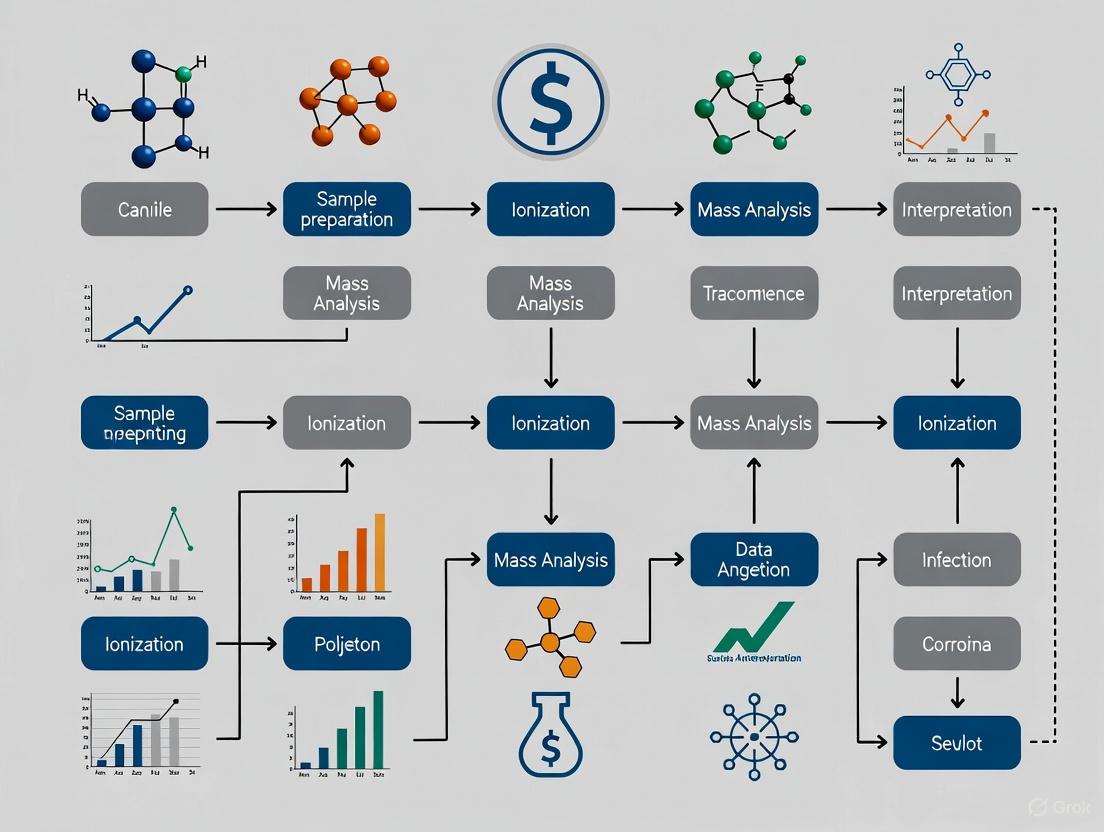
Workflow and Decision Pathway
The following diagram illustrates a logical workflow for troubleshooting and improving the detection limits of an LC-MS method.
Research Reagent Solutions
The table below lists key materials and reagents essential for developing highly sensitive MS methods, particularly for trace analysis.
Table 2: Essential Materials for Sensitive LC-MS Analysis
| Item | Function in Sensitive Analysis | Key Considerations |
|---|---|---|
| LC-MS Grade Solvents | Minimize baseline noise and chemical background caused by impurities [7]. | Essential for ultra-trace analysis. Use high-purity water, acetonitrile, and methanol. |
| Volatile Additives | Promote efficient ionization while being easily removed in the MS source to prevent contamination [5] [7]. | Formic acid, ammonium acetate, and ammonium formate are common choices. |
| Solid-Phase Extraction (SPE) Cartridges | Clean and concentrate samples, reducing matrix effects and improving LOD [6] [7]. | Select chemistry (C18, mixed-mode, etc.) based on the analyte's properties. |
| U/HPLC Columns (Sub-2µm) | Provide high chromatographic resolution, leading to sharper peaks and higher signal intensity [7]. | Requires instrumentation that can handle high back-pressures. |
| Stable Isotope-Labeled Internal Standards | Correct for variability in sample preparation and ionization suppression/enhancement (matrix effects) [6]. | Crucial for achieving accurate and precise quantification in complex matrices. |
The evolution of mass spectrometry (MS) has been fundamentally driven by the pursuit of lower detection limits, enabling scientists to detect and quantify analytes at ever-decreasing concentrations. This historical progression from early liquid chromatography-mass spectrometry (LC-MS) systems to today's ultra-high-pressure systems represents a remarkable technological journey. Over the past 45 years, detection limits have improved by nearly a factor of one million, with instruments now capable of quantitatively measuring compounds at sub-femtogram levels [8]. This enhancement in sensitivity has been crucial for trace evidence research, where analyzing minute quantities of material can determine the outcome of scientific investigations and legal proceedings. The drive toward better sensitivity has not only involved improvements to the mass spectrometer itself but also encompassed revolutionary advances in liquid chromatography, ionization techniques, and system integration, each contributing to the overall enhancement of analytical performance for challenging applications.
Historical Development of LC-MS Sensitivity
The Early Foundations of Microflow Separation Techniques
The origins of modern sensitive LC-MS techniques can be traced back to the 1970s, when researchers first began exploring microcolumn liquid chromatography. In 1974, a group at Nagoya University in Japan developed the first microcolumn LC system, incorporating elements that surprisingly resemble technologies found in today's commercial instruments [9]. These early systems utilized three distinct column configurations: (1) open microtubular columns with internal diameters of 60 µm or less; (2) long microbore capillary packed columns with internal diameters less than 1 mm; and (3) packed microcapillaries that represented a hybrid approach [9]. These pioneering systems demonstrated several inherent advantages, including better sensitivity, reduced solvent waste, and improved electrospray ionization response - benefits that continue to drive the adoption of microflow techniques today.
The 1980s witnessed the first successful efforts to interface microcolumn LC with mass spectrometry, primarily using continuous-flow fast atom bombardment (CF-FAB) and magnetic-sector MS detectors [9]. A breakthrough came in 1989 when Mosely and colleagues introduced a system that interfaced both open tubular and packed microcapillary LC with a magnetic-sector MS detector, establishing a foundation for subsequent desorption ionization techniques for analyzing polar and ionic compounds [9]. Throughout the 1990s, research continued with applications expanding to include macromolecular structures like proteins, with electrospray ionization (ESI) emerging as a preferred interface technique for coupling microflow columns to mass spectrometers.
Quantitative Analysis of Sensitivity Improvements
The rate of improvement in mass spectrometry detection limits has followed a remarkable trajectory that closely parallels Moore's Law in computing, which predicts a doubling of computing power approximately every two years. Analysis of historical data reveals that MS sensitivity has improved by a factor of nearly one million over a 30-year period from the early 1980s, a rate that actually exceeds the pace of Moore's Law [8].
Table 1: Evolution of Mass Spectrometry Detection Limits Over Time
| Time Period | Typical Detection Limits | Key Technological Drivers |
|---|---|---|
| Early 1980s | Nanogram amounts required for good signal-to-noise [8] | First commercial LC/MS interfaces |
| 1990s | Picogram to femtogram range | Improved ionization sources and triple quadrupole systems |
| 2000s | Low picogram to high femtogram range [10] | UHPLC, advanced API sources, refined MS interfaces |
| 2010s-Present | Sub-femtogram levels (0.001 part-per-trillion) [8] | Microflow LC, high-resolution MS, specialized ion sources |
When examining specific compounds, the improvement trajectory remains consistent though varies slightly by analyte. For glycine, detection limits have shown exponential improvement over time, though at a rate approximately half of Moore's Law [8]. This difference between theoretical and practical improvement rates highlights the challenges of transferring gains in instrumental sensitivity to real-world analytical applications involving complex matrices and samples.
Modern LC-MS/MS Systems and Sensitivity Enhancements
Key Instrumental Developments
The past decade has witnessed transformative developments in LC-MS instrumentation that have substantially pushed detection limits lower. Triple quadrupole mass spectrometers operating in selected reaction monitoring (SRM) or multiple reaction monitoring (MRM) modes have become the gold standard for quantitative analysis in clinical and research laboratories due to their outstanding performance characteristics [10]. The evolution of ionization sources has been particularly crucial, with techniques like electrospray ionization (ESI) and atmospheric pressure chemical ionization (APCI) undergoing significant refinement. A key innovation has been the development of thermal gradient focusing technologies, such as the Agilent Jet Stream ion source, which uses superheated nitrogen to improve droplet desolvation and ion generation, resulting in a five-fold or greater sensitivity increase compared to standard electrospray ionization [11].
High-resolution mass spectrometry (HRMS) instruments, including quadrupole time-of-flight (Q-TOF) and Orbitrap systems, have also seen substantial improvements, becoming valuable tools for both qualitative and quantitative analysis [10]. These instruments provide high resolution and mass accuracy, enabling positive confirmation of elemental composition and facilitating the identification of unknown compounds through sophisticated spectral library matching [11]. The coupling of ion mobility spectrometry (IMS) with MS has further enhanced analytical capabilities by providing additional separation dimensions and structural information through collision cross-section measurements [9] [10].
Microflow LC and Nano-ESI: Current State of Sensitivity
Recent years have seen a resurgence of interest in microflow LC-MS techniques, driven by advances in hardware, manufacturing capabilities, and software interfaces. Instead of the meter-long columns used in early systems, vendors have now produced "column-on-a-chip" devices that are self-contained and fully integrated with MS sources [9]. Modern research has demonstrated the practical benefits of these approaches for quantitative analysis, including lower detection limits, decreased matrix effects, improved precision, and significantly reduced solvent consumption due to ultralow flow rates [9].
Applications in pharmacokinetics studies highlight these advantages, with researchers using chip-based µLC-ESI-MS-MS for analysis of monoclonal antibodies and combining microsampling of dried blood spots with automated sample preparation to enable comprehensive assay miniaturization [9]. This approach supports the principles of the "3Rs" (reduce, refine, and replace) in animal studies, requiring fewer subjects and less drug compound while generating less variable data by minimizing inter-individual differences [9]. Current limitations, such as increased carryover due to low flow rates, represent technological hurdles that ongoing research continues to address through improved system design and protocols.
Troubleshooting Guides and FAQs
Frequently Asked Questions on LC-MS Sensitivity
Table 2: Essential LC-MS/MS Troubleshooting Guide for Sensitivity Issues
| Observed Problem | Potential Causes | Recommended Solutions |
|---|---|---|
| Loss of Sensitivity | Gas leaks, contaminated ion source, incorrect calibration, weak sample solvent [12] [13] | Check for gas leaks using detector, clean ion source, verify calibration, ensure sample solvent compatibility [13] |
| No Peaks in Chromatogram | Auto-sampler/syringe malfunction, column cracks, detector issues, improper sample preparation [13] | Check auto-sampler operation, inspect column for damage, verify detector function, review sample prep protocol [13] |
| High Signal in Blank Runs | System contamination, carryover from previous samples [9] [14] | Thorough system cleaning, implement adequate rinsing between samples, check for required predilution [9] |
| Peak Broadening or Distortion | Sample solvent stronger than mobile phase, excessive injection volume [12] | Use weaker injection solvent, reduce injection volume, ensure sample solvent miscibility with mobile phase [12] |
| Increased Back Pressure | Column blockage or contamination [12] | Check and replace guard column, follow column regeneration protocols, use appropriate sample cleanup [12] |
Q: What are the key advantages of LC/MS compared to other detection methods like UV? A: LC/MS systems can detect compounds that are unresolved or unobserved with UV analysis, particularly useful for impurities that may coelute or have low UV absorbance. Mass detection provides higher specificity by verifying compounds based on mass, enables multiplexed analysis through multiple detector options, and offers exceptional sensitivity with selected ion monitoring [11].
Q: How should I determine sensitivity or limit of detection in LC/MS? A: While signal-to-noise ratio (S/N) has been traditionally used, this approach can be misleading due to calculation variations. The Instrument Detection Limit (IDL) provides a more robust method for assessing detection limits and precision, offering greater confidence that your signal isn't noise [11].
Q: What is the difference between single quadrupole and triple quadrupole LC/MS systems? A: Single quadrupole systems contain one quadrupole that analyzes intact molecular ions and source-created fragments. Triple quadrupole systems include an additional collision cell and quadrupole analyzer, enabling MS/MS analysis and highly selective operational modes like Multiple Reaction Monitoring (MRM) [11].
Q: Why might my LC-MS responses not linearly correlate with concentration? A: Most molecules have linear response regions, but as you approach detection limits, response becomes less linear. Similarly, detector saturation occurs at high concentrations. Generally, three to four orders of linear dynamic range exist between these extremes, with triple quadrupole instruments typically offering broader linear range than TOF/Q-TOF instruments [11].
Experimental Protocols for Maximizing Sensitivity
Methodology for Minimizing Matrix Effects: Matrix effects, particularly ionization suppression, can significantly impact detection limits and data quality. To address this:
- Implement microflow LC at flow rates of 1-50 µL/min rather than conventional HPLC flow rates (~1 mL/min) to reduce matrix effects [9] [8]
- Use efficient sample preparation techniques including protein precipitation, solid-phase extraction, or liquid-liquid extraction to remove interfering compounds
- Employ alternative ionization sources such as atmospheric pressure chemical ionization (APCI) for compounds prone to ionization suppression in electrospray ionization [10]
- Incorporate stable isotope-labeled internal standards to correct for variability in ionization efficiency
Protocol for System Optimization for Trace Analysis: To achieve the lowest possible detection limits for trace evidence research:
- Utilize microflow or nanoflow LC systems to enhance ionization efficiency and reduce chemical noise [9]
- Implement specialized ion source technologies such as Agilent Jet Stream thermal gradient focusing for improved ion generation [11]
- Optimize injection volumes based on column dimensions - for a 2.1 mm ID column, ideal volumes typically range from 1-3 µL [12]
- Ensure sample solvent is not stronger than the mobile phase to prevent peak distortion and broadening
- For large volume injections of samples in weak solvents, employ "on-column compression" techniques to minimize band broadening [12]
The Scientist's Toolkit: Essential Research Reagents and Materials
Table 3: Key Research Reagent Solutions for Advanced LC-MS Applications
| Reagent/Material | Function/Purpose | Application Notes |
|---|---|---|
| Raptor Biphenyl Column | Separation using superficially porous particles (SPP) | Provides UHPLC-like performance on HPLC systems; higher efficiency at high flow rates [12] |
| Raptor ARC-18 Column | Sterically shielded C18 phase for challenging separations | Extended pH range (1.0-8.0); superior performance for acids and bases at low pH [12] |
| Ultra Aqueous C18 Column | High aqueous content applications | Recommended for mobile phases with >95% aqueous content [12] |
| Octafluoronaphthalene (OFN) | Standard compound for sensitivity testing | Modern standard for determining instrument detection limits [8] |
| Uracil | Void volume marker for reversed-phase HPLC | Used to experimentally estimate column void volume [12] |
Technical Diagrams and Workflows
Diagram 1: MS Sensitivity Evolution Timeline
Diagram 2: LC-MS Sensitivity Issue Troubleshooting
Technical Comparison of Ionization Techniques
Table 1: Fundamental Characteristics and Optimal Application Domains of ESI, APCI, and APPI
| Feature | Electrospray Ionization (ESI) | Atmospheric Pressure Chemical Ionization (APCI) | Atmospheric Pressure Photoionization (APPI) |
|---|---|---|---|
| Ionization Mechanism | Ion evaporation from charged droplets; formation of pre-formed ions from solution [15] [16]. | Gas-phase chemical ionization initiated by a corona discharge; reactant ions protonate or deprotonate the analyte [17]. | Gas-phase ionization by photon absorption; direct or dopant-assisted charge/proton transfer [18]. |
| Optimal Analyte Class | Polar, ionizable compounds; large biomolecules (proteins, peptides), pharmaceuticals [17] [16]. | Low to medium polarity, thermally stable small molecules (<1,500 Da) [17]. | Non-polar and weakly polar compounds (e.g., polyaromatic hydrocarbons, lipids, steroids) that are challenging for ESI/APCI [19] [18]. |
| Compatible LC Solvents | Reversed-phase (water, methanol, acetonitrile); aqueous buffers with volatile additives [15]. | Normal-phase and reversed-phase; tolerates a wider range of solvents than ESI, but not purely non-polar solvents like hexane [15]. | Normal-phase due to low solubility in aqueous reversed-phase systems; can handle non-polar solvents like toluene and hexane [19] [18]. |
| Typical Signal Intensity & Sensitivity | High for its optimal analyte classes; sensitivity can be dramatically enhanced with mobile-phase modifiers, but may reduce linear range [19] [20]. | Generally 2-4 times less sensitive than APPI for lipids; good sensitivity for its target analytes [19]. | Often provides the highest signal intensity and signal-to-noise (S/N) ratio for non-polar compounds; up to 2-4x more sensitive than APCI [19]. |
| Linear Dynamic Range | Can be nonlinear or have a reduced range when using sensitivity-enhancing modifiers [19]. | Wide, typically 4-5 orders of magnitude [19]. | Wide, typically 4-5 orders of magnitude [19] [18]. |
| Susceptibility to Matrix Effects | Highly susceptible to ion suppression from co-eluting salts and matrix components [20] [15]. | Less susceptible to matrix effects compared to ESI [20]. | Minimizes matrix effects and ion suppression, leading to cleaner data and improved analyte recovery [18]. |
Troubleshooting Guide: FAQs on Ionization Technique Selection and Optimization
FAQ 1: How do I choose between ESI, APCI, and APPI for a new analyte?
The choice should be primarily guided by the analyte's polarity and molecular weight. The following decision workflow can help guide your initial selection.
FAQ 2: My ESI signal is unstable or has suddenly dropped. What should I check?
Signal instability in ESI often stems from the ionization source or mobile phase conditions.
- Check for Source Contamination: Salts and matrix components can accumulate on the sprayer and ion entrance components, leading to unstable spraying and signal loss. Regular cleaning according to the manufacturer's guidelines is essential [15] [7].
- Optimize Sprayer Voltage and Position: An incorrectly set sprayer voltage can cause "rim emission" or "corona discharge," resulting in an unstable signal. Lower voltages can often mitigate this. Also, the sprayer's position relative to the MS inlet affects sensitivity and should be optimized—typically, more polar analytes benefit from the sprayer being farther from the inlet [15].
- Evaluate Mobile Phase and Sample for Salts: The formation of metal adducts (e.g., [M+Na]+) can scatter the signal and reduce the intensity of the protonated molecule. Use plastic vials instead of glass to avoid leaching metal ions, and ensure high-purity, LC-MS grade solvents are used. Implement rigorous sample clean-up protocols like Solid-Phase Extraction (SPE) or Liquid-Liquid Extraction (LLE) to remove interfering salts from biological matrices [15].
FAQ 3: How can I improve the sensitivity for a non-polar compound that ionizes poorly with ESI?
Switching to APCI or APPI is the most effective strategy. For optimization:
- Employ APPI with a Dopant: For analytes that do not ionize efficiently via direct photoionization, use a dopant-assisted (DA) APPI method. A dopant like toluene is first ionized by photons and then transfers charge to the analyte directly or via proton transfer from the solvent, significantly boosting ionization efficiency [18].
- Optimize LC Conditions for APCI/APPI: When using APCI or APPI, normal-phase solvent systems are often more effective due to the low solubility of many non-polar compounds in aqueous reversed-phase systems [19]. Furthermore, reducing the LC flow rate can enhance ionization efficiency in APCI by providing more time for the gas-phase reactions [20] [7].
- Fine-tune Source Parameters: For APCI, carefully optimize the vaporizer temperature to ensure complete nebulization without thermal degradation. For APPI, ensure the photon energy from the lamp (e.g., a krypton lamp) is sufficient to ionize your target analytes or the chosen dopant [17] [18].
FAQ 4: What are the best practices for minimizing matrix effects in quantitative bioanalysis?
Matrix effects, where co-eluting substances alter ionization efficiency, are a major challenge, particularly in ESI.
- * Comprehensive Sample Cleanup:* Techniques like Solid-Phase Extraction (SPE) and Liquid-Liquid Extraction (LLE) are highly effective at removing proteins, phospholipids, and other matrix interferences from biological samples before LC-MS analysis, thereby reducing ion suppression [20] [7].
- Use of APCI or APPI: APCI and APPI are generally less susceptible to matrix effects than ESI because the ionization occurs in the gas phase after the solvent and analytes have been vaporized, reducing the influence of non-volatile matrix components [20] [18].
- Chromatographic Resolution: Improve the LC separation to prevent the analyte of interest from co-eluting with matrix components. A good chromatographic separation is fundamental, as relying solely on the mass spectrometer's selectivity in modes like SRM can still lead to quantitation issues due to ion suppression [17].
- Internal Standards: Use a stable isotope-labeled internal standard (SIL-IS) for your analyte. The IS experiences the same matrix effects as the analyte, allowing for accurate correction during quantification [7].
Detailed Experimental Protocols
Protocol 1: Systematic Infusion Experiment for Ionization Technique and Polarity Selection
Objective: To empirically determine the optimal ionization technique (ESI, APCI, or APPI) and polarity (positive/negative) for a target analyte.
Materials:
- Standard solution of the target analyte (e.g., 1 µg/mL in a suitable solvent)
- LC-MS system equipped with interchangeable ESI, APCI, and APCI sources
- Infusion syringe pump
- "Tee" piece connector
- Mobile phases: 10 mM Ammonium Formate buffer, pH 2.8 and pH 8.2; HPLC-grade Methanol or Acetonitrile
Methodology:
- System Setup: Connect the infusion syringe pump containing the standard solution to the "tee" piece. The other inlets of the "tee" are connected to the LC pumps, delivering a 50:50 mixture of organic solvent (methanol/acetonitrile) and one of the ammonium formate buffers at a standard analytical flow rate (e.g., 0.2 mL/min) [17].
- Initial Tuning: For each ionization source (starting with ESI), use the instrument's autotune routine with a standard tuning compound to establish a baseline.
- Manual Parameter Optimization: With the analyte infusion ongoing, manually optimize key source parameters. Adjust voltages (capillary, cone), gas flows (nebulizing, desolvation), and temperatures (source, desolvation) to maximize the signal for the protonated/deprotonated or molecular ion of your analyte [17].
- Polarity and pH Screening: Perform Step 3 for both positive and negative ionization modes, and with both the low (pH 2.8) and high (pH 8.2) pH buffers in the mobile phase. The pH can significantly affect ionization efficiency for ionizable compounds [17].
- Technique Comparison: Repeat Steps 2-4 for the APCI and APPI sources.
- Data Analysis: Compare the signal intensity and stability (signal-to-noise ratio) obtained from all combinations. The condition (technique, polarity, pH) yielding the highest and most stable signal is the optimal choice for your method.
Protocol 2: Method for Comparing Matrix Effects Between ESI and APCI
Objective: To quantitatively assess and compare the susceptibility of an ESI-based method and an APCI-based method to matrix effects.
Materials:
- Post-extraction blank biological matrix (e.g., human plasma)
- Standard solutions of the analyte and internal standard
- Equipment for sample preparation (e.g., for LLE or SPE)
Methodology:
- Prepare Three Sets of Samples:
- Set A (Neat Solution): Prepare standards in the pure reconstitution solvent. This set defines the baseline signal.
- Set B (Post-Extraction Spiked): Extract blank matrix, then spike the analyte and IS into the cleaned extract post-extraction. The signal here is unaffected by matrix-induced ionization suppression/enhancement.
- Set C (Pre-Extraction Spiked): Spike the analyte and IS into the blank matrix and then carry out the entire extraction process. The signal here reflects the impact of any co-eluting matrix.
- LC-MS Analysis: Analyze all three sets using the identical chromatographic method on both the ESI and APCI sources.
- Calculation of Matrix Effect (ME): Calculate the ME for each source using the following formula:
ME (%) = (Peak Area Set C / Peak Area Set B) × 100%
- An ME of 100% indicates no matrix effect.
- An ME < 100% indicates ion suppression.
- An ME > 100% indicates ion enhancement.
- Comparison: Compare the ME values obtained from the ESI and APCI analyses. A value closer to 100% for APCI would confirm it is less liable to matrix effects, as suggested in the literature [20].
Research Reagent Solutions
Table 2: Essential Reagents and Materials for Ionization Optimization
| Reagent/Material | Function in Ionization Optimization | Example Use Case |
|---|---|---|
| Ammonium Formate Buffer | A volatile buffer used to adjust mobile phase pH; promotes ionization in ESI and prevents analyte degradation. | Creating pH 8.2 and 2.8 mobile phases for systematic infusion experiments to determine optimal ionization pH [17]. |
| Formic Acid | A common volatile acidic additive for LC-MS; promotes protonation in positive ion mode ESI and APCI. | Added to the mobile phase (e.g., 0.01%) to enhance [M+H]+ signal intensity for basic analytes [20] [15]. |
| Toluene (HPLC Grade) | Acts as a dopant in APPI; has a low ionization potential, is efficiently ionized by photons, and transfers charge to less easily ionized analytes. | Used in Dopant-Assisted APPI (DA-APPI) to significantly boost signal for non-polar compounds like polyaromatic hydrocarbons [18]. |
| Cyclohexane (Analytical Grade) | A solvent for Liquid-Liquid Extraction (LLE); effectively extracts non-polar analytes from aqueous biological matrices. | Used in sample prep to extract levonorgestrel from human plasma, reducing matrix effects before LC-MS analysis [20]. |
| Solid-Phase Extraction (SPE) Cartridges | A sample preparation tool for selective adsorption, wash, and elution of analytes; removes salts and phospholipids that cause ion suppression. | Cleaning up plasma or urine samples prior to ESI-MS to achieve lower detection limits and more robust quantification [7]. |
Troubleshooting Guides & FAQs
Frequently Asked Questions
Q1: My mass spectrometer shows a sudden loss of sensitivity. What are the most common causes?
A sudden drop in sensitivity is a common issue in trace analysis where maximum signal is crucial. The problem often originates from the ion source or sample introduction system.
- Clogged ESI Spray Needle: This is frequently caused by non-volatile components in your samples or mobile phase. These components deposit on the needle's inner wall, eventually clogging it. To prevent this, ensure thorough sample preparation to remove non-volatile components and always use volatile buffers for LC-MS analysis [21].
- Contaminated Ion Optics: Over time, the ion transfer tube and other optics can become contaminated, reducing ion transmission efficiency. Regular cleaning is essential. For instance, the Ion Transfer Tube should be removed and sonicated in a 50:50 methanol/water solution with 20% formic acid for 30 minutes, rinsed with water, sonicated in methanol, and dried with nitrogen gas [22].
- Vacuum Leaks: A leak in the system can contaminate the sample and damage the instrument, leading to sensitivity loss. Use a leak detector to check common problem areas such as gas supply lines, column connectors, and the EPC connections [13].
Q2: My instrument failed its mass calibration. What steps should I take to resolve this?
Failed mass calibration compromises the accuracy of your trace-level identifications. The following steps can help restore calibration.
- Check Spray Stability: An unstable spray is a common culprit. Ensure your electrospray is stable and consistent during the calibration process [23].
- Use Fresh Calibrant: Over time, the calibration mixture (cal mix) can degrade or become contaminated. Prepare a fresh, high-quality cal mix for the calibration procedure [23].
- Perform Diagnostics and Recalibrate: If the problem persists, run diagnostic tests such as "Orbitrap transmission" and "isotope ratio." Follow up with the appropriate coarse and fine mass calibrations as specified in your instrument's manual [23]. Mass calibration should be performed every 3-6 months as part of routine maintenance [22].
Q3: What is the recommended procedure for shutting down the system for an extended period?
Proper shutdown procedures are critical for maintaining instrument health and avoiding problems upon restart.
- Flush the LC System: To remove any buffers or additives and prevent microbial growth, flush the entire LC system first with a 50:50 mixture of solvent (methanol or acetonitrile) and water, followed by a flush with 100% solvent [22].
- System Standby: After flushing, the system can be placed into a standby mode. For short periods (less than 24 hours), standby alone may be sufficient, but flushing is still good practice [22].
Troubleshooting Common Instrumental Issues
Problem: Unstable Spray or Needle Clogging
| Possible Cause | Recommended Solution |
|---|---|
| Non-volatile components in sample/mobile phase | Improve sample clean-up; use only volatile buffers (e.g., ammonium formate/acetate) [21]. |
| Use of divert/bypass valve without make-up flow | Add a second HPLC pump to supply clean solvent to the needle when flow is diverted to waste [21]. |
Problem: Power Failure and System Venting
| Symptom | Action Plan |
|---|---|
| Log file shows system reboot; pressure reading indicates bad vacuum. | A main power failure can cause the system to vent. Once power returns, the system may start automatically, but a manual bakeout is often required to obtain operating vacuum [21]. |
| Frequent, unattended power failures. | Install an Uninterruptible Power Supply (UPS) or a power fail detector to protect the instrument [21]. |
Problem: Turbomolecular Pump Overheating and Shutting Off
| Indicator | Resolution |
|---|---|
| Pump switches off automatically; Tune software shows error messages or overheating status. | The pump may be blocked, or its cooling fans may have failed. Immediately shut down the mass spectrometer as per the operator's manual and contact a field service engineer to prevent permanent damage [21]. |
Mass Analyzer Performance for Trace Analysis
The selection of a mass analyzer is a critical determinant for achieving the low detection limits required in trace evidence research. The table below summarizes key performance metrics of common mass analyzers, with a focus on specifications from a detailed Q Exactive study [24].
| Analyzer Type | Mass Resolution (at m/z 200) | Mass Accuracy (ppm) | Scan Speed | Optimal Application in Trace Analysis |
|---|---|---|---|---|
| Quadrupole | Unit (0.5-1.0 Th) | - | Very Fast | Targeted quantification (e.g., MRM on Triple Quads); high ion current capacity [24]. |
| Time-of-Flight (TOF) | >20,000 | <5 | Fast | Untargeted screening; full-scan sensitivity [24]. |
| Orbitrap | 17,500 - 140,000 | <3 | Moderate to Fast | High-confidence identification and quantification of complex mixtures [24]. |
| Q Exactive (Quadrupole-Orbitrap) | 17,500 - 140,000 [24] | <3 [24] | Top 10 HCD method: 1s cycle time [24] | Proteomics; multiplexed MS/MS; requires high resolution and accuracy [24]. |
Experimental Protocol: Optimizing Source Position for Sensitivity
Objective: To empirically determine the optimal ion source position that maximizes signal-to-noise (S/N) for your specific analyte and flow conditions, thereby improving detection limits [22].
Materials:
- Mass spectrometer (e.g., TSQ Quantis, Altis, Fortis)
- HPLC system with injector and a short column
- Standard solution of your analyte at a concentration that yields ~10:1 S/N
- Appropriate mobile phase
Methodology:
- System Equilibration: Turn on both the LC and MS systems and allow them to stabilize for at least 30 minutes.
- Isocratic Elution: Set up an isocratic method on the HPLC using the expected mobile phase composition and flow rate.
- Loop Injections: Perform repeated loop injections of your analyte standard.
- Parameter Adjustment: For each injection, slightly adjust the source position parameters (e.g., left/right, up/down, fore/aft). Note: On some instruments like the TSQ Altis, Quantis, and Fortis, the needle position is fixed and should not be adjusted [22].
- Data Recording: Record a raw data file for each injection and integrate the analyte peaks.
- Data Analysis: Compare the peak areas and, more importantly, the background noise levels across the different source positions. The optimal position is the one that maximizes the peak area without a proportional increase in noise [22].
The Scientist's Toolkit: Essential Research Reagent Solutions
| Item | Function in Trace Analysis |
|---|---|
| Volatile Buffers (e.g., Ammonium Formate, Ammonium Acetate) | Replace non-volatile phosphate buffers in LC mobile phases to prevent ion source clogging and maintain stable spray and high sensitivity [21]. |
| Methanol & Acetonitrile (HPLC/MS Grade) | High-purity solvents are used for mobile phases, sample reconstitution, and system flushing to minimize background noise and chemical interference [22]. |
| Formic Acid | A volatile additive used to acidify mobile phases, promoting protonation of analytes in positive electrospray ionization (ESI+) for improved ion generation [22]. |
| Calibration Mixture (Cal Mix) | A solution of compounds with known, accurately determined masses. Essential for periodic mass calibration to ensure the accuracy of analyte identification [23]. |
| Sonicating Cleaning Solution (50:50 MeOH/H₂O + 20% Formic Acid) | A potent cleaning solution used in an ultrasonic bath to remove tenacious contamination from ion transfer tubes, sweep cones, and other source components [22]. |
Troubleshooting Workflow for Sensitivity Loss
The following diagram outlines a systematic approach to diagnosing and resolving a common and critical problem in trace analysis: the loss of sensitivity.
Technical Support & Troubleshooting Center
This guide provides targeted troubleshooting for UHPLC and NanoLC systems, with a focus on maintaining the high separation efficiency necessary for improving detection limits in mass spectrometry-based trace evidence research.
Pressure Abnormalities
Pressure-related issues are common and can halt experiments. Table 1 outlines symptoms and solutions.
Table 1: Troubleshooting Guide for Pressure Problems
| Symptom | Potential Cause | Solution |
|---|---|---|
| Pressure Too High [25] [26] | Blockage in system (most common at in-line frit or column head) [25]. | Isolate blockage by disconnecting components sequentially starting downstream [25]. Replace in-line frit (0.2 µm for ≤2-µm particles) or back-flush column [25]. |
| Pressure Too Low [25] [26] | Air in the pump, faulty check valve, or a leak [25]. | Purge pump to remove air bubbles [25]. Check for leaks and verify pump delivery by performing a timed collection of mobile phase [25]. |
| Pressure Spikes [26] | Particulate buildup or column packing disruption [26]. | Check and replace in-line filters or guard columns. If column is suspected, reverse-flush if permitted [26]. |
| Gradual Pressure Increase | Normal column aging or accumulation of debris [25]. | Track pressure over time. Use and regularly replace an in-line frit and guard column to protect the analytical column [25]. |
Peak Shape Anomalies
Peak shape issues like tailing and fronting directly impact resolution and detection limits. Table 2 details common causes and fixes.
Table 2: Troubleshooting Guide for Peak Shape Problems
| Symptom | Potential Cause | Solution |
|---|---|---|
| Tailing Peaks [27] [28] [26] | Secondary interactions with active sites on stationary phase (e.g., basic compounds with silanol groups) [27] [26]. | Use high-purity silica (type B) or polar-embedded phase columns [27]. Add a competing base like triethylamine to the mobile phase [27]. |
| Column overload (too much mass or volume) [28] [26]. | Reduce injection volume or sample concentration [28] [26]. | |
| Physical column issues (voids, blocked frit) [27] [26]. | Replace column or pre-column frit. Back-flush column if possible [27]. | |
| Fronting Peaks [27] [26] | Column overload [26]. | Reduce the amount of sample injected [27]. |
| Sample dissolved in a solvent stronger than the mobile phase [27]. | Dissolve or dilute the sample in the starting mobile phase or a weaker solvent [27]. | |
| Channels in the column or a blocked frit [27]. | Replace the column [27]. | |
| Broad Peaks [27] [28] | Extra-column volume too large [27] [28]. | Use short capillaries with narrow internal diameter (e.g., 0.13 mm for UHPLC) and low-volume flow cells [27]. |
| Detector time constant (response time) set too long [27]. | Set response time to less than 1/4 of the narrowest peak's width at half-height [27]. | |
| Column degradation or voiding [27] [28]. | Replace column. Avoid pressure shocks and aggressive pH conditions [27]. |
Retention Time and Signal Stability
Inconsistent retention times and signal loss compromise quantitative accuracy, especially in trace analysis. Table 3 addresses these critical issues.
Table 3: Troubleshooting Guide for Retention Time and Signal Problems
| Symptom | Potential Cause | Solution |
|---|---|---|
| Retention Time Shifts [28] [26] | Unstable mobile phase composition, pH, or flow rate [26]. | Prepare mobile phase consistently and verify flow rate via timed collection [26]. Use a column oven for stable temperature [28] [26]. |
| Column not equilibrated or is aging [28] [26]. | Equilibrate column with 10-15 column volumes of mobile phase [28]. | |
| No Peaks / Loss of Signal [28] [29] | Complete loss of prime on pump (especially organic phase) [29]. | Manually purge and prime pumps to remove stubborn air pockets [29]. |
| Air in autosampler fluidics, clogged needle, or leaking injector seal [27]. | Flush autosampler, replace needle or seal [27]. | |
| Detector lamp failure or incorrect settings [28]. | Replace old lamp (typically >2000 hours) and check detector settings [28]. | |
| Ghost Peaks [26] | Contaminants in mobile phase, solvents, or sample vial [26]. | Use fresh, high-purity HPLC-grade solvents and mobile phases [30] [26]. |
| Carryover from previous injections [26]. | Clean autosampler, needle, and injection valve; run blank injections to confirm [26]. |
Frequently Asked Questions (FAQs)
1. My peaks have disappeared entirely. Where should I start looking? Begin by isolating the problem to the LC or MS. First, check if the MS has a stable electrospray by visually inspecting for a spray at the needle tip [29]. Then, directly infuse your sample into the MS source, bypassing the LC. If the signal returns, the issue is in the LC system, most commonly a pump that has lost prime or has an air lock [29]. Manually purging the pumps is often the solution.
2. How can I quickly differentiate if a problem originates from the column, injector, or detector? A practical approach is to observe which peaks are affected [26]. If all peaks show the same problem (e.g., all are tailing or broad), the issue is likely a physical column problem or a system-wide effect. If only one or a few specific peaks are affected, it is likely a chemical interaction specific to those analytes and the column. If the problem appears in the early part of the chromatogram or involves inconsistent peak areas, suspect the injector [26]. Detector issues often manifest as baseline noise or a sudden loss of sensitivity across all analytes [26].
3. What is the most effective way to optimize my method for the highest efficiency in the shortest time? For the highest plate count in a given analysis time, a systematic approach is best [31]. Start by choosing an appropriate particle size and column length for your desired speed. Then, optimize the linear velocity (flow rate) using the van Deemter equation. For ultimate performance, consider a three-parameter optimization that simultaneously adjusts particle size, column length, and eluent velocity to operate at the kinetic performance limit, often requiring specialized equipment and smaller particles [31].
4. Why do I see ghost peaks in my blank injections, and how can I eliminate them? Ghost peaks are typically caused by contaminants or carryover [26]. Common sources are contaminated mobile phase water, leachables from solvent bottles or tubing, or a contaminated autosampler needle. To resolve this, run a series of blank injections to confirm. Then, replace all mobile phases with fresh, HPLC-grade solvents, clean the autosampler and replace the needle if necessary, and use a guard column to capture contaminants before they reach the analytical column [26].
Experimental Protocols for Enhanced Separation
Protocol: Systematic Troubleshooting of Peak Shape
Objective: To diagnose and correct the root cause of tailing or fronting peaks in a reversed-phase UHPLC method.
- Initial Assessment: Inject a standard mixture and note the asymmetry factor for all peaks. Determine if the issue affects all peaks or is analyte-specific [26].
- Reduce Sample Load: Dilute the sample 10-fold and re-inject. If tailing/fronting improves, the issue was mass or volume overload. Optimize injection parameters accordingly [28] [26].
- Check Solvent Compatibility: Ensure the sample is dissolved in a solvent that is the same or weaker strength than the starting mobile phase. Re-prepare the sample in the mobile phase and re-inject [27] [28].
- Investigate Column Chemistry: If tailing persists for specific analytes (e.g., bases), consider secondary interactions. Switch to a more inert stationary phase (high-purity silica, hybrid, or charged surface reversed-phase) [27].
- Inspect Column Hardware: If all peaks are tailing, the column may have a void or blocked inlet frit. Replace the guard cartridge first. If unresolved, back-flush the column or replace it [27] [26].
Protocol: Estimation and Verification of System Pressure
Objective: To establish a reference pressure for a method and diagnose deviations.
- Calculate Expected Pressure: Use the following formula to estimate the pressure drop across the column [25]:
- P (psi) = 1500 × L (mm) × η (cP) × F (mL/min) / dc (mm)² × dp (µm)²
- Where L = column length, η = mobile phase viscosity, F = flow rate, dc = column diameter, dp = particle size.
- Measure System Reference Pressure: Install a new column and set a standard mobile phase (e.g., 50:50 methanol-water). Set flow rate and temperature, equilibrate, and record the pressure. This is your system reference [25].
- Isolate Pressure Problems: If operating pressure is abnormal, progressively disconnect fittings starting from the column outlet and moving upstream, recording the pressure after each step. A significant pressure drop after a component indicates the location of a blockage [25].
Workflow and Relationship Visualizations
Logical Troubleshooting Pathway
UHPLC Performance Optimization Relationship
The Scientist's Toolkit: Essential Research Reagents & Materials
Table 4: Key consumables and materials for robust UHPLC and NanoLC methods.
| Item | Function & Importance |
|---|---|
| HPLC-Grade Solvents & Water [30] | High-purity solvents are critical for low UV background, minimal contaminant peaks (ghost peaks), and stable baselines, especially in trace analysis [30] [26]. |
| In-Line Filters & Guard Columns [25] [26] | Placed between the injector and analytical column, they protect the expensive column from particulate matter and contaminated samples, extending its life and preventing pressure increases [25] [26]. |
| High-Purity Silica (Type B) Columns [27] | Columns packed with high-purity, low-metal-content silica minimize secondary interactions (e.g., with silanol groups), reducing peak tailing for basic compounds and improving peak shape [27]. |
| Viper or Fingertight Fitting Capillaries [27] | These low-volume, zero-dead-volume fitting systems are essential for UHPLC and NanoLC to minimize extra-column volume, which can cause significant peak broadening and loss of efficiency [27]. |
| Appropriate Buffers & Additives [27] [30] | Buffers control pH for consistent retention of ionizable analytes. Additives like triethylamine can compete with analytes for active sites on the stationary phase, improving peak shape [27] [30]. |
Matrix effects, ion suppression, and background contamination are critical challenges in mass spectrometry that directly impact the accuracy, sensitivity, and reliability of analytical results, particularly in trace evidence research. These phenomena occur when components in a sample matrix interfere with the ionization process of target analytes, leading to suppressed or enhanced signals, or when contaminants introduce erroneous data. In quantitative liquid chromatography-mass spectrometry (LC-MS), matrix effects detrimentally affect accuracy, reproducibility, and sensitivity, potentially causing false negatives or positives and compromising detection limits. This technical support center provides comprehensive troubleshooting guides and FAQs to help researchers identify, mitigate, and compensate for these issues in their experimental workflows.
Frequently Asked Questions (FAQs)
1. What exactly are matrix effects and ion suppression in mass spectrometry? Matrix effects occur when compounds coeluting with your analyte interfere with the ionization process in the mass spectrometer, leading to either suppression or enhancement of the analyte signal. Ion suppression is a specific manifestation of matrix effects that results in a loss of signal response. These interferences detrimentally affect method accuracy, reproducibility, and sensitivity [32] [33] [34].
2. Which ionization techniques are more susceptible to ion suppression? Electrospray Ionization (ESI) is generally more susceptible to ion suppression than Atmospheric Pressure Chemical Ionization (APCI). This is because ionization in ESI occurs in the liquid phase, where competition for charge and space in the droplets can occur, whereas in APCI, the analyte is vaporized before gas-phase ionization, resulting in less competition [33] [34].
3. How can I quickly check if my method is suffering from matrix effects? The post-column infusion method is a powerful qualitative technique for this purpose. It involves infusing a constant flow of your analyte into the LC eluent while injecting a blank sample extract. A dip or rise in the baseline indicates regions of ionization suppression or enhancement in the chromatogram, allowing you to identify problematic retention times [32] [33] [34].
4. My blank matrix is not available. How can I compensate for matrix effects? The Standard Addition Method (SAM) is particularly useful when a blank matrix is unavailable, such as for endogenous analytes. This method involves adding known amounts of the analyte to the sample itself at multiple concentration levels. By measuring the response at each level, you can construct a calibration curve that inherently corrects for the matrix effect present in that specific sample [32].
5. What is the best internal standard to correct for matrix effects? Stable Isotope-Labeled Internal Standards (SIL-IS) are considered the gold standard. Because they have nearly identical chemical and chromatographic properties to the analyte but a different mass, they experience the same matrix effects and can precisely compensate for them. If SIL-IS are too expensive or unavailable, a coeluting structural analogue can be a viable alternative [32] [34].
Troubleshooting Guides
Guide 1: Diagnosing Matrix Effects and Ion Suppression
Problem: Inconsistent quantification, loss of sensitivity, or poor reproducibility between samples.
Solution: Systematically evaluate the presence and impact of matrix effects using established protocols. The table below summarizes the primary detection methods.
Table 1: Methods for Detecting Matrix Effects
| Method Name | Description | Key Outcome | Limitations |
|---|---|---|---|
| Post-Column Infusion [33] [34] | A constant flow of analyte is infused post-column while a blank matrix extract is injected. | Qualitative identification of chromatographic regions with ion suppression/enhancement. | Does not provide quantitative data; requires additional setup. |
| Post-Extraction Spike [32] [34] | Compare the signal of an analyte in neat solvent vs. an analyte spiked into a blank matrix extract. | Quantitative measurement of the absolute matrix effect at a specific concentration. | Requires a blank matrix. |
| Slope Ratio Analysis [34] | Compare the slope of a calibration curve in solvent to one in a post-extraction spiked matrix. | Semi-quantitative assessment of matrix effects over a range of concentrations. | Requires a blank matrix and more extensive work. |
Guide 2: Strategies to Minimize or Compensate for Matrix Effects
Problem: Confirmed matrix effects are impacting data quality.
Solution: A combination of sample preparation, chromatographic optimization, and calibration strategies can be employed. The following diagram illustrates a logical decision workflow for addressing matrix effects based on your sensitivity requirements and resource constraints.
Diagram 1: Strategy selection for matrix effects.
1. Minimizing Matrix Effects:
- Improve Sample Clean-up: Utilize selective extraction techniques like Solid-Phase Extraction (SPE) or Liquid-Liquid Extraction (LLE) to remove interfering compounds from the sample [32] [35]. Simple sample dilution can also be effective if assay sensitivity allows [32].
- Optimize Chromatography: Adjust the chromatographic method (e.g., mobile phase composition, gradient, column type) to increase the separation between the analyte and coeluting interferences. Even a small shift in retention time can significantly reduce matrix effects [32] [33].
- Adjust MS Parameters: Switching from ESI to APCI can often reduce susceptibility to matrix effects [33] [34]. Using a divert valve to direct the initial and late eluting solvent front to waste can also prevent source contamination [34].
2. Compensating for Matrix Effects:
- Stable Isotope-Labeled Internal Standards (SIL-IS): This is the most effective compensation technique. The SIL-IS coelutes with the analyte and undergoes identical ionization suppression, allowing for an accurate correction of the analyte's response [32] [34].
- Standard Addition Method: This method is ideal for situations where a blank matrix is unavailable, as it accounts for the specific matrix of each individual sample [32].
- Matrix-Matched Calibration: Preparing calibration standards in a blank matrix that matches the sample can help correct for matrix effects, though it requires a sufficient quantity of blank matrix [34].
Experimental Protocols
Protocol 1: Post-Column Infusion for Qualitative Matrix Effect Assessment
This protocol helps visualize the regions of ion suppression/enhancement in your chromatographic run [33] [34].
1. Materials and Equipment:
- LC-MS system
- Syringe pump
- T-piece connector
- Analyte standard solution
- Prepared blank sample extract
2. Procedure:
- Step 1: Set up the syringe pump to deliver a continuous, low flow of your analyte standard solution.
- Step 2: Connect the output of the syringe pump to a T-piece installed between the HPLC column outlet and the MS ion source.
- Step 3: With the pump and infusion running, establish a stable baseline signal for the analyte in the mass spectrometer.
- Step 4: Inject the blank sample extract onto the LC column and start the chromatographic method.
- Step 5: Observe the signal of the infused analyte. Any depression (suppression) or elevation (enhancement) of the baseline indicates the elution of matrix components that interfere with ionization.
Protocol 2: Post-Extraction Spike for Quantitative Matrix Effect Measurement
This protocol provides a quantitative value for the matrix effect [32] [34] [36].
1. Materials:
- Analyte standard solution
- Blank matrix (e.g., plasma, urine, tissue homogenate)
- Neat solvent (mobile phase)
2. Procedure:
- Step 1: Prepare Sample A by spiking a known concentration of the analyte into the neat solvent.
- Step 2: Prepare Sample B by subjecting the blank matrix to your entire sample preparation procedure (extraction, dilution, etc.). After preparation, spike the same concentration of analyte into this prepared extract.
- Step 3: Analyze both Sample A and Sample B using your LC-MS method.
- Step 4: Calculate the Matrix Effect (ME) using the formula:
- ME (%) = (Peak Area of Sample B / Peak Area of Sample A) × 100%
- A value of 100% indicates no matrix effect. <100% indicates suppression, and >100% indicates enhancement.
The Scientist's Toolkit
This table lists key reagents and materials essential for investigating and mitigating the discussed challenges.
Table 2: Essential Research Reagent Solutions
| Item | Function/Benefit |
|---|---|
| Stable Isotope-Labeled Internal Standards (SIL-IS) | Gold standard for compensating matrix effects; behaves identically to the analyte during sample prep and ionization but is distinguished by MS [32] [34]. |
| Structural Analogues as Internal Standards | A cost-effective alternative to SIL-IS; must be a compound that coelutes with the analyte and has similar physicochemical properties [32]. |
| Selective Solid-Phase Extraction (SPE) Sorbents | Used for sample clean-up to remove interfering phospholipids, proteins, and salts, thereby reducing the matrix load entering the MS [32] [35]. |
| High-Purity Mobile Phase Additives (e.g., Formic Acid) | Reduces background contamination and chemical noise; trace impurities in lower-grade additives can cause significant ion suppression [32]. |
| Appropriate Chromatographic Columns | Columns designed for specific separations (e.g., Zorbax Eclipse Plus for basic compounds) can improve peak shape and resolution, minimizing coelution [35]. |
Advanced Applications: Pushing Sensitivity Boundaries in Biomedical and Forensic Analysis
Forensic proteomics applies protein analysis to forensic science, offering a powerful alternative when DNA evidence is degraded, insufficient, or unavailable [37]. This field enables the identification of body fluids, estimation of postmortem intervals (PMI), and determination of the cause of death by characterizing protein signatures in trace evidence like hair, bone, and bodily fluids [37]. Liquid Chromatography-Mass Spectrometry (LC-MS) is the cornerstone analytical technique for these investigations, though the path to reliable results is often fraught with technical challenges related to sensitivity and contamination [38]. This technical support center provides targeted troubleshooting guides and FAQs to help researchers navigate these complexities and improve detection limits for trace evidence research.
Troubleshooting Guide: Common LC-MS Issues in Forensic Proteomics
1. Problem: High Background Noise or Signal Suppression
- Question: My LC-MS data shows high background noise, obscuring peptide signals. What could be the cause?
- Answer: This is frequently caused by contaminating polymers. Polyethylene glycol (PEG) from skin creams, pipette tips, or surfactant-based cell lysis methods (e.g., Tween, Triton X-100) are common sources. Polysiloxanes (PS) from siliconized surfaces can also be a culprit [38].
- Solution:
- Avoid using surfactant-based lysis methods. If you must use them, implement rigorous solid-phase extraction (SPE) clean-up steps to remove surfactants prior to analysis [38].
- Use LC-MS grade solvents and high-quality water that has not been stored for extended periods [38].
- Wear gloves during sample preparation, but consider removing them once proteins are digested to avoid introducing polymer contamination from the gloves themselves [38].
2. Problem: Inconsistent or Low Peptide Yields
- Question: My protein digest seems successful, but peptide recovery is low and inconsistent. What should I check?
- Answer: Peptides can adsorb onto the surfaces of sample vials and pipette tips, especially at low concentrations [38].
- Solution:
- Use "high-recovery" LC vials engineered to minimize adsorption.
- "Prime" vessels with a sacrificial protein like Bovine Serum Albumin (BSA) to saturate adsorption sites [38].
- Avoid completely drying down peptide samples; leave a small amount of liquid to increase recovery [38].
- Limit sample transfers and consider "one-pot" sample preparation methods (e.g., SP3, FASP) to minimize surface contact [38].
3. Problem: Unidentified Keratin Contamination
- Question: A large portion of my identified peptides originate from keratin. How can I reduce this contamination?
- Answer: Keratins from skin, hair, and fingernails are the most abundant protein contaminants in proteomic labs [38].
- Solution:
- Perform all sample preparation in a laminar flow hood to prevent dust and skin particles from entering samples [38].
- Do not wear clothing made from natural fibers like wool in the laboratory [38].
- Wear gloves at all times and replace them after touching potentially contaminated surfaces like stopwatches or laboratory notebooks [38].
4. Problem: Poor Chromatographic Performance for Peptides
- Question: My peptide peaks are broad or poorly shaped. How can I improve the chromatography?
- Answer: This can result from using trifluoroacetic acid (TFA) in the mobile phase, which suppresses peptide ionization, or from residual salts in the sample [38].
- Solution:
Frequently Asked Questions (FAQs)
Q1: Why is proteomics a viable alternative when DNA evidence fails? Proteomics is viable because proteins are more stable than DNA in many postmortem conditions. While DNA may degrade rapidly, proteins can persist and provide critical information for body fluid identification, PMI estimation, and cause of death determination long after DNA has become unviable [37].
Q2: What are the key applications of forensic proteomics? The key applications include:
- Body Fluid and Tissue Identification: Determining the origin of a biological stain [37].
- Postmortem Interval (PMI) Estimation: Analyzing the predictable degradation of proteins like GAPDH and eEF1A2 in skeletal muscle to estimate time since death [37].
- Cause of Death Determination: Identifying protein biomarkers associated with specific causes, such as Apolipoprotein A1 (ApoA1) levels in drowning cases or 14-3-3 protein isoforms in Sudden Infant Death Syndrome (SIDS) [37].
Q3: What advanced strategies can improve detection limits in LC-MS? Improving detection limits involves a holistic approach:
- Sample Pre-concentration: Use techniques like evaporation/reconstitution or on-line SPE to concentrate analytes [7].
- Chromatographic Enhancements: Utilize nano-LC or micro-LC with reduced inner diameter columns and lower flow rates to increase analyte concentration and ionization efficiency [7].
- MS Optimization: Fine-tune ionization source parameters and leverage high-resolution mass spectrometry (HRMS) or ion mobility spectrometry (IMS) to reduce chemical noise [7].
Q4: How can I account for protein modifications that affect analysis? Be aware that reagents like urea, used in lysis buffers, can decompose to isocyanic acid and cause carbamylation of free amine groups on peptides. This modification must be accounted for in your peptide identification software by instructing it to look for carbamylation as a variable modification [38].
Experimental Protocols for Key Forensic Applications
Protocol 1: Estimating Postmortem Interval (PMI) from Skeletal Muscle
Objective: To identify and quantify specific protein degradation markers (e.g., GAPDH, eEF1A2) in skeletal muscle tissue for PMI estimation [37].
Methodology:
- Sample Homogenization: Homogenize skeletal muscle tissue in a suitable buffer (e.g., RIPA buffer) without surfactants that may contaminate the MS.
- Protein Digestion: Reduce, alkylate, and digest the protein extract using trypsin.
- Sample Clean-up: Desalt the resulting peptides using a reversed-phase SPE cartridge to remove salts and impurities.
- LC-MS/MS Analysis:
- Column: Use a C18 nano-flow or UHPLC column for high separation efficiency.
- Gradient: Employ a water/acetonitrile gradient with formic acid as an additive.
- Mass Spectrometer: Operate in data-dependent acquisition (DDA) mode on a high-resolution instrument (e.g., Q-TOF or Orbitrap) to fragment peptides for identification.
- Data Analysis: Search MS/MS data against a protein sequence database. Quantify the relative levels of GAPDH, eEF1A2, and other relevant proteins (e.g., alpha-enolase, malate dehydrogenase) across samples of known PMI to build a degradation model [37].
Protocol 2: Differentiating Drowning as a Cause of Death from Blood
Objective: To measure specific protein biomarkers in blood serum that can differentiate drowning from other causes of death [37].
Methodology:
- Sample Preparation: Deplete high-abundance proteins from blood serum or plasma using an immunoaffinity column.
- Digestion and Clean-up: Digest the remaining proteins with trypsin and clean up the peptides with SPE.
- LC-MS Analysis in PRM Mode:
- Chromatography: Separate peptides on a reversed-phase UHPLC column.
- Mass Spectrometry: Use a targeted method like Parallel Reaction Monitoring (PRM) on a high-resolution mass spectrometer for highly sensitive and accurate quantification of peptides from Apolipoprotein A1 (ApoA1) and alpha-1 antitrypsin [37].
- Quantification and Validation: Use stable isotope-labeled versions of the target peptides as internal standards for precise quantification. Construct Receiver Operating Characteristic (ROC) curves to validate the ability of ApoA1 and alpha-1 antitrypsin levels to classify drowning cases [37].
Workflow Visualization
Forensic Proteomics Workflow
LC-MS Protein Identification Process
Data Presentation
Table 1: Protein Biomarkers for Postmortem Interval (PMI) Estimation [37]
| Protein Marker | Biological Sample | Observed Change | Forensic Application |
|---|---|---|---|
| GAPDH | Skeletal Muscle | Predictable proteolysis | Early to mid-PMI estimation |
| eEF1A2 | Skeletal Muscle | Predictable proteolysis | Early to mid-PMI estimation |
| Alpha-enolase | Various Tissues | Correlation with PMI | Supporting PMI estimation |
| Malate dehydrogenase | Various Tissues | Correlation with PMI | Supporting PMI estimation |
| Peroxiredoxin 2 | Various Tissues | Correlation with PMI | Supporting PMI estimation |
Table 2: Protein Biomarkers for Cause of Death Determination [37]
| Protein Marker | Biological Sample | Observed Change | Forensic Application |
|---|---|---|---|
| Apolipoprotein A1 (ApoA1) | Blood Serum | Increased levels | Drowning identification |
| Alpha-1 antitrypsin | Blood Serum | Decreased levels | Drowning identification |
| 14-3-3 protein isoforms | Brainstem/Medulla | Reduced levels | SIDS risk assessment |
The Scientist's Toolkit: Research Reagent Solutions
Table 3: Essential Materials for Forensic Proteomics Experiments
| Item | Function/Application | Key Considerations |
|---|---|---|
| Trypsin | Protein digestion into peptides for LC-MS analysis. | Use sequencing-grade purity for reliable and reproducible cleavage [38]. |
| Solid-Phase Extraction (SPE) Cartridges | Sample clean-up and desalting. | Reversed-phase C18 cartridges are standard for peptide purification [38]. |
| UHPLC Column | High-resolution separation of complex peptide mixtures. | Sub-2µm particle C18 columns provide superior separation efficiency [7]. |
| LC-MS Grade Solvents | Mobile phase preparation. | Essential for minimizing background noise and contamination [38] [7]. |
| Formic Acid | Mobile phase additive for LC-MS. | Preferred over TFA to avoid ion suppression of peptides [38]. |
| Stable Isotope-Labeled Peptides | Internal standards for absolute quantification. | Critical for accurate measurement of biomarker concentrations in PRM/SRM assays. |
Core Concepts and Techniques FAQ
What is Mass Spectrometry Imaging (MSI) and how does it benefit drug metabolism studies? Mass Spectrometry Imaging (MSI) is a powerful analytical technique that detects, quantifies, and visualizes the spatial distribution of molecules directly from thin tissue sections. It functions as a "molecular microscope," allowing for simultaneous, label-free, and compound-specific imaging of a drug and its metabolites within tissue structures [39] [40]. This provides a significant advantage over traditional methods. Unlike autoradiography, which cannot distinguish a parent drug from its radiolabeled metabolites, MSI provides specific molecular identity. Furthermore, it reveals the spatial distribution of compounds that conventional LC-MS/MS analysis of tissue homogenates lacks [40].
Why is MS/MS (MS2) data crucial for untargeted metabolomics in drug studies? In a biological sample, many small molecules can have similar or identical masses in the initial MS1 scan. MS2 data provides a "chemical fingerprint" by breaking the parent molecule into smaller fragments, revealing its chemical substructures [41]. This information is essential for accurately annotating unknown drug metabolites in complex samples. While MS1 data alone might be acceptable for targeted analyses, MS2 is indispensable for confident identification in untargeted metabolomics, as it helps differentiate between isomeric compounds that have the same mass but different structures [41].
What are the main ionization techniques used in MSI for pharmaceutical applications? The two most commonly applied MSI techniques in pharmaceutical research are:
- MALDI-MSI (Matrix-Assisted Laser Desorption/Ionization): A versatile soft ionization method that allows analysis of a wide mass range. A matrix is applied to the tissue section to absorb laser energy and facilitate desorption and ionization of molecules [39] [40].
- DESI-MSI (Desorption Electrospray Ionization): An ambient ionization technique performed under atmospheric pressure, which often requires less sample preparation compared to MALDI [39].
Troubleshooting Guides: Improving Detection Limits
Guide 1: Addressing Low Signal-to-Noise Ratio
A low signal-to-noise ratio is a primary factor limiting detection. Improving it involves both boosting the analyte signal and reducing background noise [42].
- Problem: Signal is too low for trace-level drug or metabolite detection.
Potential Causes & Solutions:
- Suboptimal Ionization Efficiency: Fine-tune MS source parameters, including spray voltage, gas flows, and temperatures. For less polar compounds, consider alternative ionization techniques like APCI [7].
- Inefficient Sample Introduction: Utilize nano-LC or micro-LC systems. Columns with smaller inner diameters and lower flow rates increase analyte concentration at the detector and enhance ionization efficiency [7].
- Insufficient Sample Cleanup: Implement rigorous sample preparation techniques like Solid-Phase Extraction (SPE) to remove interfering proteins and salts, which reduces chemical noise and concentrates the analytes of interest [7].
Problem: Baseline noise is obscuring the analyte signal.
- Potential Causes & Solutions:
- Pump Pulsations: Flow rate fluctuations are a major noise source. A pulse damper is considered essential for trace analysis [42].
- System Contamination: Implement rigorous cleaning protocols for both LC and MS components and use only the highest quality LC-MS grade solvents and reagents [7].
- Electronic Noise: Ensure proper grounding and shielding. Electronic noise suppression features in the instrument should be optimized [42].
Guide 2: Troubleshooting Metabolite Identification
- Problem: Inability to confidently identify drug metabolites from complex biological data.
- Potential Causes & Solutions:
- Lack of Fragmentation Data: Ensure MS/MS data is acquired for all samples in untargeted workflows. Data-Dependent Acquisition (DDA) is currently the preferred method for metabolomics studies [41].
- High False Discovery Rate: Use advanced data-processing strategies. Combining dose-response experiments with Stable Isotope Tracing (SIT) has been shown to effectively and comprehensively identify drug metabolites with high efficacy. Features that show a dose-response relationship and contain an isotope pair from a labeled drug are high-confidence candidates [43].
- Inability to Distinguish Isomers: Remember that MS2 alone may not differentiate stereoisomers, as they can produce identical fragmentation patterns. Additional separation techniques, such as optimizing LC parameters (mobile phase, column selectivity), are required [41] [42].
Experimental Protocols
Protocol: Drug Metabolite Profiling Using Dose-Response and Stable Isotope Tracing
This protocol, adapted from recent research, outlines a effective methodology for comprehensive drug metabolite identification [43].
1. Sample Preparation and Incubation
- Prepare incubation samples (e.g., using human liver S9 fractions) containing the drug (e.g., Rosiglitazone) and its stable isotope-labeled analog (e.g., ROS-D4).
- Conduct a dose-response experiment by incubating with varying concentrations of the drug.
- After incubation, add enzymes like β-glucuronidase and sulfatase to deconjugate phase II metabolites.
- Stop the reaction with an acid like acetic acid, then centrifuge and filter the supernatant.
- Purify and concentrate analytes using Solid-Phase Extraction (SPE) with a C18 cartridge [43].
2. LC-MS/MS Analysis
- Instrumentation: Use a high-resolution mass spectrometer (e.g., Orbitrap Fusion Lumos) coupled with a UHPLC system.
- Chromatography: Employ a reversed-phase C18 column with a gradient elution using mobile phases such as 0.1% formic acid in water and methanol.
- MS Acquisition: Acquire full-scan MS1 data at high resolution (e.g., 120,000). Subsequently, acquire MS2 spectra using a collision energy (e.g., 30-35 eV) for structural elucidation [43].
3. Data Processing
- First Stage (Dose-Response): Process the data to detect all ion features. Screen for features whose abundance correlates with the increasing dose of the drug.
- Second Stage (Stable Isotope Tracing): From the dose-responsive features, screen for the presence of isotope pairs (e.g., native and deuterium-labeled pairs). These high-confidence candidates are then validated using MS/MS fragmentation data [43].
The workflow for this experimental approach is summarized in the following diagram:
Data Presentation
Table 1: Key Strategies for Improving Detection Limits in LC-MS
| Strategy Category | Specific Technique | Key Benefit | Application Note |
|---|---|---|---|
| Sample Preparation | Solid-Phase Extraction (SPE) | Reduces matrix effects, concentrates analyte | Selective adsorption/elution improves signal-to-noise [7]. |
| Protein Precipitation | Removes interfering proteins from biological fluids | Use precipitating agents like organic solvents or acids [7]. | |
| Chromatography | Nano-LC / Micro-LC | Increases analyte concentration, enhances ionization | Lower flow rates (200-500 nL/min) and narrow-bore columns are used [7]. |
| Sub-2μm Particle Columns | Provides enhanced resolution and peak capacity | Reduces band broadening, improving sensitivity [7]. | |
| Mass Spectrometry | High-Resolution MS (HRMS) | Provides improved selectivity and sensitivity | Reduces chemical noise in complex samples [7]. |
| Optimizing Ionization | Enhances ion generation and transmission | Fine-tune spray voltage, gas flows, and temperatures [7]. | |
| Data Acquisition | Parallel Reaction Monitoring (PRM) | Improved selectivity/sensitivity for targeted analysis | [7] |
| Data-Dependent Acquisition (DDA) | Enables MS2 for identification in untargeted work | Preferred over DIA for metabolomics [41]. |
Table 2: Research Reagent Solutions for Drug Metabolism Studies
| Reagent / Solution | Function | Example & Specification |
|---|---|---|
| Stable Isotope-Labeled Drug | Serves as an internal standard for tracking metabolite formation; enables identification via isotope peak pairs. | Rosiglitazone-D4 (purity ≥96%); labeled on benzene ring [43]. |
| Enzyme Systems | Mimics in vivo metabolic reactions (Phase I & II). | Human liver S9 fractions (20 mg/mL protein) [43]. |
| Hydrolyzing Enzymes | Deconjugates Phase II metabolites (glucuronides, sulfates) back to their parent form for detection. | β-Glucuronidase (>85,000 units/mL); Sulfatase (11 units/mL) [43]. |
| Cofactors | Provides essential components for enzymatic metabolic reactions. | NADP (1 mM), Glucose-6-phosphate (3 mM) for S9 incubation [43]. |
| LC-MS Calibrants | Ensures mass accuracy and instrument performance validation. | Pierce Peptide Retention Time Calibration Mixture; HeLa Protein Digest Standard [44]. |
| SPE Cartridges | Purifies and concentrates analytes from complex biological matrices prior to analysis. | C18 Cartridge (e.g., 50 mg sorbent, 55–105 μm) [43]. |
Advanced Methodologies and Signaling Pathways
The relationship between different mass spectrometry acquisition modes and their applications in drug metabolism studies can be visualized as follows:
The illicit drug market is highly dynamic, constantly evolving with the rapid emergence of New Psychoactive Substances (NPS) designed to be perceived as legal substitutes for scheduled compounds [45]. Once a compound becomes prohibited, new unscheduled molecules quickly appear, enlarging the library of psychoactive substances [45]. Among these, new synthetic opioids (NSO) constitute one of the fastest-growing NPS subclasses, with 73 compounds detected in Europe between 2009 and 2021 alone [45]. These substances present a significant analytical challenge due to their extreme potency, structural diversity, and the low concentrations required to produce physiological effects, pushing the limits of conventional detection methods [46] [45]. This technical support article addresses these challenges within the broader thesis context of improving detection limits in mass spectrometry for trace evidence research, providing targeted methodologies and troubleshooting guidance for researchers and forensic scientists.
FAQs: Addressing Core Analytical Challenges
What are the primary classes of emerging synthetic opioids and their key analytical challenges?
Emerging synthetic opioids are broadly categorized into fentanyl analogues and non-fentanyl structured compounds [45]. The non-fentanyl NSOs include several distinct chemical classes:
- Diphenylethylpiperazines (e.g., MT-45)
- Cinnamylpiperazines (e.g., 2-methyl AP-237)
- Cyclohexylbenzamides (e.g., U-47700, AH-7921)
- 2-Benzylbenzimidazoles (Nitazenes) [45]
- Benzimidazolones (e.g., Brorphine) [45]
The principal analytical challenge is their high potency, which necessitates exceptionally low limits of detection—often at least 0.01 ng/mL in biological matrices—to identify their use [45]. Furthermore, the rapid pace of emergence requires analytical methods that can be easily expanded to include new compounds [46].
How can I improve LC-MS/MS sensitivity for detecting trace-level fentanyl analogues?
Enhancing sensitivity for potent fentanyl analogues requires optimized sample preparation and instrument parameters. A validated screening procedure for 38 fentanyl analogues and five other new opioids in whole blood using liquid chromatography-tandem mass spectrometry (LC-MS/MS) provides a robust methodology [46]. Key steps include:
- Sample Extraction: Basic extraction of blood samples with ethyl acetate [46].
- Chromatographic Separation: Achieving separation using a gradient of mobile phase composition and a gradient of the flow rate, achieving a run time of 13 minutes [46].
- Detection: Utilizing dynamic multiple reaction monitoring (MRM) for high-sensitivity detection [46].
- Method Validation: This approach has demonstrated limits of detection in the range of 0.01–0.20 ng/mL for various fentanyl analogues [46].
Why is my mass spectrometry system showing a loss of sensitivity or no peaks?
Common instrumental issues that cause sensitivity loss or absence of peaks can be systematically diagnosed. The table below outlines frequent problems and their solutions.
Table: Troubleshooting Common Mass Spectrometry Issues
| Problem | Potential Cause | Recommended Action |
|---|---|---|
| Loss of Sensitivity [13] | Gas leaks, contaminated source, or loose connections. | Check for gas leaks using a leak detector. Inspect and tighten gas filters, shutoff valves, EPC connections, weldments, and column connectors [13]. |
| No Peaks [13] | Issue with detector, auto-sampler, syringe, or column. | Verify auto-sampler and syringe function. Check the column for cracks. Ensure the detector flame is lit (if applicable) and gases are flowing correctly [13]. |
| Poor Chromatography/Quantification [44] | System performance issues or incorrect calibration. | Recalibrate the instrument using certified calibration solutions. Verify LC acquisition method settings and consider fractionating samples to reduce complexity [44]. |
What methods are available to distinguish isomeric novel psychoactive substances?
Distinguishing isomeric NPS is a major challenge in forensic toxicology [47]. While standard GC-MS or LC-MS/MS methods sometimes fail, advanced techniques can be employed:
- Chiral Chromatography Columns: These columns are specifically designed to separate enantiomers [47].
- Ion Mobility Spectrometry-MS (IMS-MS): This technique separates ions based on their size, shape, and charge, providing an additional dimension of separation orthogonal to chromatography and mass spectrometry [47].
- Advanced Fragmentation Models: Utilizing different collision energies or fragmentation patterns can help differentiate isomers with similar structures [47].
Experimental Protocols for Advanced Detection
LC-MS/MS Screening for Fentanyl Analogues and New Opioids
This protocol is adapted from a published procedure for the simultaneous qualitative screening of 43 new opioids in whole blood [46].
1. Sample Preparation:
- Extract a whole blood sample (e.g., 1 mL) with ethyl acetate under basic conditions [46].
- Evaporate the organic layer to dryness under a gentle stream of nitrogen.
- Reconstitute the dried extract in a suitable mobile phase for LC-MS/MS analysis.
2. Liquid Chromatography Conditions:
- Column: Appropriate C18 reversed-phase column.
- Mobile Phase: Gradient elution using water and methanol or acetonitrile, both modified with ammonium formate or another volatile buffer.
- Gradient: Utilize a gradient of mobile phase composition and a gradient of the flow rate to achieve optimal separation of analytes within a 13-minute run time [46].
- Column Temperature: Maintained at a constant temperature (e.g., 40°C).
3. Mass Spectrometry Detection:
- Ionization: Electrospray Ionization (ESI) in positive mode.
- Detection Mode: Dynamic Multiple Reaction Monitoring (MRM).
- Optimization: For each target analyte, optimize MS parameters including precursor ion, product ions, collision energy, and source-dependent parameters. The method should be capable of detecting compounds at concentrations as low as 0.01 ng/mL [46].
4. Data Analysis:
- Identify compounds based on their retention times and MRM transitions.
- Note that the method may not achieve full separation of some isomeric compounds [46].
Workflow for Seized Drug Analysis using Ambient Mass Spectrometry
For rapid screening of seized materials with minimal sample preparation, ambient mass spectrometry techniques such as Desorption Electrospray Ionization (DESI) and Direct Analysis in Real Time (DART) are highly valuable [48] [47]. These techniques require no or minimal sample preparation, enable analysis within seconds, and are suitable for coupling with portable mass spectrometers for on-site analysis [48].
The following diagram illustrates the logical workflow for analyzing seized drugs using these advanced techniques:
The Scientist's Toolkit: Essential Research Reagents & Materials
Successful detection of trace-level emerging drugs relies on a suite of specialized reagents and materials. The following table details key items for setting up and validating analytical methods.
Table: Essential Research Reagents and Materials for Trace Drug Analysis
| Item | Function / Application | Example / Citation |
|---|---|---|
| Certified Calibration Solutions | Calibrating the mass spectrometer to ensure mass accuracy and system performance. | Pierce Calibration Solutions; used for recalibration and verifying instrument settings [44]. |
| HeLa Protein Digest Standard | Checking overall LC-MS system performance and troubleshooting sample preparation issues. | Pierce HeLa Protein Digest Standard (Cat. No. 88328); tests sample clean-up methods and acts as a control [44]. |
| Peerformance Testing Mixture | Diagnosing and troubleshooting the liquid chromatography system and gradient performance. | Pierce Peptide Retention Time Calibration Mixture (Cat. No. 88321) [44]. |
| High-Purity Solvents & Buffers | Used in mobile phases and sample preparation to minimize background noise and ion suppression. | LC-MS grade methanol, acetonitrile, and volatile buffers like ammonium formate or acetate [46]. |
| Solid Phase Extraction (SPE) Cartridges | Extracting and concentrating analytes from complex biological matrices like blood or urine. | Various phases (e.g., C18, mixed-mode) for clean-up and pre-concentration of samples [47]. |
| LC-MS/MS System with MRM | The core platform for sensitive, specific, and high-throughput identification and quantification of target opioids. | Systems capable of dynamic MRM for screening dozens of compounds simultaneously [46]. |
The continuous emergence of novel synthetic opioids demands equally dynamic advancements in mass spectrometry. By implementing highly sensitive and specific LC-MS/MS protocols, utilizing ambient ionization techniques for rapid screening, and adhering to rigorous troubleshooting and calibration practices, researchers can effectively push the boundaries of detection limits. The methodologies and guidance provided here are intended to support scientists in adapting to the rapidly changing landscape of seized drug analysis, thereby contributing to public health and safety efforts.
This technical support center provides troubleshooting guides and FAQs for researchers applying Single-Cell ProtEomics by Mass Spectrometry (SCoPE-MS) to push detection limits in trace evidence and biomedical research.
SCoPE-MS Workflow and Core Principle
SCoPE-MS is designed to overcome the challenges of measuring the low protein abundance in single mammalian cells. It substantially alters standard bulk LC-MS/MS methods by using tandem mass tags (TMT) and a carrier channel to enable peptide identification and quantification from single cells [49].
Figure 1: The core SCoPE-MS experimental workflow involves single-cell isolation, lysis, multiplexing, and data analysis. [49]
The core innovation uses a carrier channel comprising ~200 cells, which provides enough peptide ions for confident sequence identification. The single-cell channels (typically 8-10) are labeled with different TMT tags and combined with this carrier. The carrier channel mitigates peptide losses and enables identification, while the TMT reporter ions allow quantification of each peptide in the individual single cells [49] [50].
Figure 2: The SCoPE-MS principle: The carrier channel aids identification, and reporter ions enable single-cell quantification. [49] [50]
Detailed Experimental Protocol
The following is a detailed SCoPE-MS protocol for mammalian cells. [51]
Plate Preparation
- Add 1 µL of HPLC-grade water to each well of a 96-well or 384-well plate.
- Cover the plate and freeze at -80°C until cell sorting.
Cell Preparation
- For suspension cells: Transfer 1-2 mL of cell culture to a tube and proceed to centrifugation.
- For adherent cells:
- Aspirate the media from the plate.
- Wash with PBS (2 mL for a 6 mm plate, 4 mL for a 10 mm plate) at 37°C.
- Add Accutase (1 mL for a 6 mm plate, 2 mL for a 10 mm plate) and incubate at 37°C for 5 minutes.
- Pipette the Accutase to dislodge cells and transfer to a tube.
- Centrifuge cells at 500 RCF for 2 minutes at 4°C.
- Remove supernatant, resuspend pellet in cold PBS, and centrifuge again.
Cell Sorting
- Use a FACS sorter to deposit single cells into the pre-prepared plate wells.
- Ensure a bulk carrier sample (e.g., 200 cells/µL) is also sorted for later use.
Flash-Freeze Lysis
- Place the cell plate at -80°C for at least 5 minutes.
- Preheat a thermocycler to 90°C and pause it.
- Transfer the plate to the thermocycler and run at 90°C for 10 minutes, then hold at 4°C.
Digestion and TMT Labeling
- Centrifuge the plate briefly.
- Add 1 µL of a solution containing 200 mM TEAB and 10 ng/µL trypsin to each well.
- Digest on a thermocycler at 37°C or 45°C for 3 hours.
- Add 0.5 µL of the appropriate 85 mM TMT label to each well.
- Carrier channel: TMT-126
- Single-cell channels: TMT-127N, 128N, 128C, 129N, 129C, 130N, 130C, 131
- Incubate at room temperature for 1 hour.
- Quench the reaction by adding 0.5 µL of 0.5% hydroxylamine and incubate for 30 minutes at room temperature.
Sample Pooling and MS Submission
- To one well in a TMT set, add 1 µL of the bulk carrier and 0.5 µL of 20% formic acid (FA).
- Aspirate the entire volume and transfer it sequentially to all other wells in the same set, combining them.
- Transfer the pooled mixture to an MS vial insert.
- Adjust the volume to 12 µL with water or by evaporation.
- Submit for LC-MS/MS analysis (e.g., on a Q Exactive instrument), injecting 10 µL.
SCoPE-MS Performance and Applications
SCoPE-MS enables the quantification of hundreds to thousands of proteins from individual mammalian cells, allowing for the deconstruction of cell populations. [49] [52]
Table 1: Quantitative Performance of SCoPE-MS
| Performance Metric | Result | Experimental Context |
|---|---|---|
| Proteins Quantified | >1,000 proteins [49] | Differentiating mouse embryonic stem cells |
| Cell Types Distinguished | Jurkat vs. U-937 cells [49] | Two blood cancer cell lines (11 μm diameter) |
| Proteins with Cell-Type Specific Expression | 107 proteins (FDR < 2%) [49] | Based on a two-sample t-test |
| Correlation with Transcriptome Data | Coordinated mRNA-protein covariation [49] | Many genes show distinct regulatory patterns |
A key application is cell type identification. When single-cell proteomes from Jurkat and U-937 blood cancer cell lines are projected by principal component analysis (PCA), they cluster distinctly by cell type. [49] This demonstrates that SCoPE-MS can stratify cell types based on their proteomic profiles, which is crucial for investigating heterogeneous samples like tumors or differentiating stem cells.
The Scientist's Toolkit: Essential Research Reagents
Table 2: Key Reagents and Materials for SCoPE-MS
| Reagent/Material | Function in SCoPE-MS | Example/Specification |
|---|---|---|
| Tandem Mass Tags (TMT) | Multiplexed labeling of peptides from single cells and carrier | 10-plex or 11-plex TMT sets [49] [51] |
| Trypsin | Proteolytic digestion of proteins into peptides | Promega Trypsin Gold, 10 ng/µL [51] |
| TEAB Buffer | Provides alkaline pH environment for digestion and labeling | 200 mM for digestion [51] |
| HPLC-grade Water | Low-background solvent for plate preparation and sample handling | Used for plate pre-wetting [51] |
| Formic Acid (FA) | Acidifies the sample to stop digestion and for LC-MS compatibility | 20% FA for sample acidification before MS [51] |
| Hydroxylamine | Quenches the TMT labeling reaction | 0.5% solution [51] |
Frequently Asked Questions (FAQs)
General and Conceptual
Q1: What is the fundamental principle that allows SCoPE-MS to work with single-cell inputs? SCoPE-MS turns a limitation of isobaric tagging into a strength. The carrier channel (~200 cells) provides a sufficient ion count for triggering MS2 scans and identifying peptide sequences. The TMT tags then allow for the quantification of these identified peptides back to the individual single-cell channels, whose signal is amplified by the carrier, effectively multiplying sensitivity. [49] [50]
Q2: What is the typical protein quantification depth achieved with SCoPE-MS? In validated studies, SCoPE-MS has been used to quantify over 1,000 proteins from single mammalian cells, such as differentiating mouse embryonic stem cells. The exact number can vary based on cell size, sample preparation quality, and instrument sensitivity. [49] [52]
Q3: Can SCoPE-MS distinguish between different cell types? Yes. PCA analysis of single-cell proteomes from distinct human cancer cell lines (e.g., Jurkat and U-937) shows clear clustering by cell type. Furthermore, statistical tests (t-tests) can identify specific proteins that are differentially expressed between cell types. [49]
Protocol and Troubleshooting
Q4: During cell sorting, a bulk carrier is mentioned. What is its purpose and how is it prepared? The bulk carrier, typically labeled with TMT-126, serves two critical functions: 1) It provides a high-abundance source of ions to ensure reliable peptide identification via MS2 sequencing. 2) It reduces adsorption losses of single-cell peptides to surfaces (e.g., LC columns) because the carrier peptides are more likely to be lost. The carrier is prepared by sorting about 200 cells into a tube, processing them similarly to single cells, and labeling the resulting peptides. [49] [51]
Q5: Why is mechanical lysis (sonication) preferred over chemical lysis with detergents? Chemical lysis often requires detergents like SDS, which are incompatible with MS and must be removed by cleanup procedures. These cleanup steps can incur substantial protein losses, which is catastrophic for single-cell samples. Mechanical lysis via focused acoustic sonication effectively lyses cells without introducing MS-incompatible chemicals, thereby obviating cleanup and minimizing losses. [49]
Q6: The protocol mentions leaving one TMT channel empty (e.g., 130N). Why is this done? Leaving one channel empty is a critical noise control. The signal measured in this empty channel reflects the background noise and any isotopic cross-contamination from adjacent channels. This measured noise level can be used to estimate the signal-to-noise ratio (SNR) for the experiment and validate that the signals in the single-cell channels are genuine and significantly above background. [49]
Q7: What are common reasons for low protein identification rates in a SCoPE-MS run?
- Inefficient lysis: Ensure proper sonication efficiency.
- Cell loss or lysis during sorting: Verify cell viability and sorting accuracy into the plate.
- Incomplete digestion or labeling: Check enzyme activity and reagent freshness.
- MS instrument sensitivity: Optimize MS methods for low-input samples, such as increasing ion accumulation time. [49]
- Carrier amount too low: The carrier must be sufficiently abundant to trigger identifications.
Q8: How can I improve the signal-to-noise ratio for TMT reporter ions?
- Optimize carrier-to-single-cell ratio: A very high carrier amount can lead to co-isolation interference, which dampens measured ratios. Test different ratios (e.g., 100x, 200x).
- Use MS3 or real-time search methods: If available on your instrument, these methods can significantly reduce co-isolation interference.
- Ensure proper quenching: Incomplete quenching of the TMT reaction can lead to high background.
- Check for contamination: Contaminants in solvents or on labware can increase chemical noise. [49]
Direct Analysis in Real Time Mass Spectrometry (DART-MS) has emerged as a powerful ambient ionization technique for forensic chemistry, enabling rapid chemical analysis of samples in their native state with minimal or no preparation. This technology addresses critical needs in forensic laboratories dealing with case backlogs, difficult-to-analyze samples, and the identification of emerging drugs such as new psychoactive substances [53]. Since its inception in 2004, DART-MS has been increasingly adopted for a wide range of forensic applications, including the detection of drugs of abuse, due to its ability to provide a near-complete chemical profile of a sample within seconds [53] [54]. The technique is particularly valuable for improving detection limits in trace evidence research, as it allows for direct analysis of complex samples without the need for time-consuming chromatographic separation.
Technical Foundations of DART-MS
Fundamental Principles
The DART-MS process utilizes a heated metastable gas (typically helium) to desorb and ionize compounds directly from a sample surface at atmospheric pressure [53] [55]. The ionization mechanism begins with the creation of a plasma containing metastable species. After charged species are neutralized via an electrode, the resulting stream of excited-state atoms interacts with atmospheric water vapor to produce reagent ions that subsequently ionize the analyte molecules through proton transfer reactions [53]. This process can generate both positive and negative ions, allowing for flexibility in analyzing various compound classes [55].
Operational Workflow
The following diagram illustrates the fundamental workflow and ionization mechanism of DART-MS:
Experimental Protocols for Drug Detection
Standard DART-MS Analysis of Solid Samples
The analysis of solid samples, including potential drugs of abuse, follows a straightforward protocol that requires minimal sample preparation:
Instrument Setup: Configure the DART ion source with helium gas flow between 1.5-3.0 L/min and set the grid electrode voltage to 350 V for both positive and negative ion modes [53] [56].
Temperature Optimization: Establish optimal desorption temperature by testing standards at multiple temperatures (e.g., 100°C, 150°C, 200°C, 250°C, 350°C, 450°C). Most compounds show best response at 350°C in positive ion mode [56].
Sample Introduction: For powdered samples, dip a glass capillary tube into the material and place the coated end directly into the helium plasma stream. For solid materials, section the sample to a size that can be held with tweezers and position it in the DART gas stream [56].
Data Collection: Acquire mass spectra using a time-of-flight mass spectrometer with mass accuracy sufficient to distinguish between compounds with similar nominal masses [56].
Enhanced Sampling Techniques for Complex Matrices
For complex samples or when improved reproducibility is required, several enhanced sampling approaches have been developed:
Solid Phase Extraction (SPE): Utilizes coated metal meshes, wires, or SPME tips for sample cleanup and preconcentration, simplifying complex mixture analysis [53].
Thermal Desorption (TD)-DART-MS: Employs an auxiliary thermal desorption unit that allows for controlled sample insertion and desorption, increasing reproducibility [53].
High-Temperature Modifications: Techniques like Joule-heating thermal desorption (JHTD)-DART-MS enable desorption temperatures exceeding 750°C for challenging analytes [53].
Essential Research Reagents and Materials
Table 1: Key Research Reagent Solutions for DART-MS Analysis
| Item | Function | Application Example |
|---|---|---|
| Helium Gas | Primary source gas for metastable species generation | Production of excited-state atoms for ionization [53] |
| Glass Microcapillaries | Sample introduction tool for solids and liquids | Direct analysis of powdered samples [56] |
| Methanol (HPLC-grade) | Solvent for standard preparation and dilution | Sequential dilution of analytical standards [56] |
| Solid Phase Extraction Tips | Sample cleanup and preconcentration | Simplifying complex mixture analysis [53] |
| Certified Reference Standards | Method validation and compound identification | Creating spectral libraries for drug identification [56] |
Data Analysis and Interpretation
Chemometric Approaches
The analysis of DART-MS data frequently employs statistical and chemometric tools to enhance classification and differentiation of samples. Principal Component Analysis (PCA) is the most frequently used unsupervised approach for feature extraction, reducing the dimensionality of mass spectral data to highlight distinguishing features [53]. This method creates principal components consisting of multiple m/z values that help separate data based on sample origin, composition, or other characteristics, enabling reliable classification of unknown samples against reference libraries.
Quantitative Considerations
While traditionally considered a screening technique, recent advances have shown DART-MS may be capable of providing quantitative results. The implementation of internal standards, improved sample introduction systems, and advanced data processing methods have enhanced the quantitative potential of DART-MS [53]. However, when using direct sampling methods without standardized introduction volumes, the technique remains primarily qualitative or semi-quantitative [56].
Troubleshooting Guides and FAQs
Common Operational Issues and Solutions
Table 2: DART-MS Troubleshooting Guide for Common Experimental Issues
| Problem | Potential Causes | Solutions |
|---|---|---|
| Weak or No Signal | Incorrect gas flow, improper positioning, low temperature | Verify gas flow rate (1.5-3.0 L/min), check sample positioning in plasma stream, optimize desorption temperature [53] [56] |
| High Background | System contamination, impure source gas | Run solvent blanks, clean sampling areas, use high-purity gas (99.995% or better) [14] |
| Inaccurate Mass Assignment | Calibration drift, instrumental error | Recalibrate mass spectrometer using certified reference standards [14] |
| Poor Reproducibility | Inconsistent sampling, manual introduction variability | Implement automated sampling systems, use thermal desorption units for controlled introduction [53] |
Frequently Asked Questions
Q: What types of samples can be analyzed using DART-MS for drug detection? A: DART-MS can analyze a wide variety of sample types including powders, tablets, plant materials, liquids, and surfaces. The technique has been successfully applied to detect drugs on diverse surfaces such as concrete, human skin, and currency [55].
Q: Is DART-MS suitable for quantitative analysis of drugs? A: While primarily used for screening and identification, DART-MS can provide quantitative results with proper method validation. Implementation of internal standards, controlled sample introduction, and advanced data processing methods improve quantitative capability [53].
Q: How does DART-MS compare to traditional GC-MS for drug analysis? A: DART-MS offers significant advantages in analysis speed (seconds per sample versus minutes for GC-MS) and requires minimal or no sample preparation. However, GC-MS may provide better separation of complex mixtures and has established regulatory acceptance for confirmatory analysis [53].
Q: What are the detection limits for typical drugs using DART-MS? A: Detection limits vary by compound but can reach as low as 100 μg/L for some analytes like coumarin and cinnamaldehyde. Less sensitive compounds may have detection limits around 10 mg/L [56].
Q: Can DART-MS distinguish between isobaric compounds? A: The high mass accuracy of time-of-flight mass spectrometers typically coupled with DART sources can resolve many isobaric compounds. However, some challenging pairs may require additional separation techniques or MS/MS capabilities for definitive identification [56].
Application in Drug Detection and Analysis
DART-MS has proven particularly valuable for the rapid screening and identification of drugs of abuse in forensic contexts. The technique's ability to analyze samples in their native form without extensive preparation makes it ideal for high-throughput scenarios. Specific applications include:
New Psychoactive Substances (NPS) Identification: Rapid characterization of emerging synthetic drugs that may not be included in traditional targeted methods [53].
Pharmaceutical Analysis: Detection of active pharmaceutical ingredients and potential adulterants in commercial products [56].
Drug Profiling: Chemical attribution of seized drugs to determine origin or batch consistency using chemometric analysis of spectral data [53].
The experimental workflow for drug analysis follows a logical progression from sample to result, as shown in the following diagram:
Future Perspectives and Research Needs
The future development of DART-MS for drug detection focuses on several key areas:
Enhanced Reproducibility: Continued refinement of automated sample introduction systems to improve quantitative capabilities and method validation [53].
Advanced Instrumentation: Implementation of ion mobility spectrometry as an additional separation dimension to increase confidence in compound identification [53].
Standardized Protocols: Development of validated methods and standardized operating procedures to facilitate adoption in regulatory environments [53].
Miniaturization and Portability: Exploration of field-deployable DART-MS systems for point-of-need analysis in law enforcement and border security applications [55].
As DART-MS technology continues to evolve, its role in forensic drug analysis is expected to expand, potentially transitioning from a primarily screening technique to a confirmatory method with appropriate validation and quality control measures.
Technical Support Center
Troubleshooting Guides
Sensitivity Loss and Ion Suppression
This guide helps diagnose and fix issues related to reduced signal intensity and ion suppression effects.
| Symptom & Possible Cause | Solution |
|---|---|
| Ion Suppression: Caused by co-eluting matrix components from complex biological samples [57]. | Optimize sample preparation (e.g., use SPE or hybridization techniques) to remove interferences [57] [58]. |
| Ion Source Contamination: Buildup affecting ionization efficiency [57]. | Perform routine cleaning and maintenance of the ion source and LC components [57]. |
| Sample Cleanliness: Dirty samples leading to signal loss [58]. | Improve sample clean-up; cleaner extracts yield better sensitivity in microflow LC-MS/MS [58]. |
| Suboptimal Ionization: Inefficient ion transmission or spray instability [57]. | Tune source parameters (gas flow, temperature, capillary voltage) and consider adding trace DMSO to enhance ionization [59]. |
Chromatographic Performance and Robustness
This guide addresses problems with separation quality, peak shape, and system stability.
| Symptom & Possible Cause | Solution |
|---|---|
| Broad or Tailing Peaks: Could be from column overloading, contamination, or a voided column [28]. | Reduce injection volume/mass, wash the column with appropriate solvents, or replace the column if necessary [28]. |
| Varying Retention Times: Caused by temperature fluctuations, system leaks, or improper solvent mixing [28]. | Use a column oven, check for and replace leaking fittings, and ensure pumps are mixing solvents correctly [28]. |
| Column Clogging: More susceptible with nano-flow systems analyzing complex samples like plasma [60]. | Switch to a more robust micro-flow column (e.g., 1 mm ID) and ensure adequate sample cleanup [60] [59]. |
| High Backpressure: Can limit application scope [60]. | Select columns known for lower backpressure, such as the HALO ES-C18 [60]. |
Frequently Asked Questions (FAQs)
Q1: What is the primary sensitivity advantage of microflow LC-MS/MS over conventional analytical flow methods?
A1: Studies have demonstrated that microflow LC-MS/MS can provide up to a sixfold improvement in sensitivity for challenging analytes like antisense oligonucleotides. This is largely because the lower flow rates (typically 10-100 µL/min) improve ionization efficiency in the electrospray source compared to higher analytical flows [58].
Q2: I need high sensitivity but also high throughput and robustness. Is microflow a good compromise?
A2: Yes. Microflow LC-MS/MS effectively bridges the gap between the high sensitivity of nano-flow and the high robustness of analytical flow. It offers significantly enhanced robustness and throughput compared to nano-flow systems, with one study showing a single column can analyze over 7,500 samples without performance loss, while maintaining excellent sensitivity [59].
Q3: My sensitivity is still lower than expected after switching to microflow. What should I check first?
A3: Focus on sample cleanliness. The sensitivity gain from microflow LC is highly dependent on having a clean sample extract. The cleaner the sample, the greater the sensitivity improvement you will observe. Evaluate your sample preparation method; techniques like solid-phase extraction (SPE) or hybridization may be necessary instead of simple protein precipitation [58].
Q4: Which microflow LC columns are recommended for proteomic applications?
A4: A systematic evaluation of commercial columns found that most, including PepMap C18, HALO ES-C18, and Acquity UPLC Peptide BEH C18, are suitable for routine proteomics. The PepMap C18 column was noted as an outstanding option for plasma samples due to its high loading capacity and maintained peak shape. The HALO ES-C18 exhibited relatively lower backpressure [60].
Q5: How does sample requirement compare between nano-flow and micro-flow LC-MS/MS?
A5: While nano-flow offers the highest sensitivity with minimal sample, micro-flow requires slightly more. One study found that only about 5-10 times more sample was needed on the micro-flow system to achieve similar numbers of peptide and protein identifications as on a nano-flow system, which is often an acceptable trade-off for the massive gain in robustness and throughput [59].
Experimental Protocols
Protocol 1: Establishing a Base Microflow LC-MS/MS Method for Sensitivity Gain
This protocol outlines the key steps to set up a microflow LC-MS/MS method to achieve significant sensitivity improvements.
1. Instrument Configuration:
- LC System: Use a standard UHPLC system capable of delivering precise gradients at flow rates of 10-100 µL/min.
- Mass Spectrometer: A sensitive tandem mass spectrometer, such as a triple quadrupole for quantitative analysis or an Orbitrap for discovery proteomics, is required [57] [59].
- Column: Select a suitable microflow column (e.g., 1.0 mm internal diameter, 15 cm length, C18 phase). The PepMap C18 is a robust starting point [60].
2. Initial Method Parameters:
- Flow Rate: Begin with 50 µL/min [59].
- Mobile Phase:
- A: 0.1% Formic acid in LC-MS grade water.
- B: 0.1% Formic acid in LC-MS grade acetonitrile.
- Gradient: Optimize for your analyte. A linear gradient from 5% B to 35-38% B over 30-60 minutes is a typical starting point for complex mixtures [59] [61].
- Column Temperature: Maintain at a consistent temperature (e.g., 40-50°C) using a thermostatically controlled oven [28].
3. MS/MS Acquisition Tuning:
- Ion Source Tuning: Carefully optimize parameters like capillary voltage, nebulizing gas pressure, and desolvation temperature for your specific analyte and flow rate [57].
- MRM/PRM Transition Selection (for quantitation): Select precursor and product ions to maximize signal-to-noise ratios. Tune collision energies for each transition [57].
- Data-Dependent Acquisition (DDA for discovery): Use a rapid acquisition method (e.g., 28 Hz) to adequately sample the narrower peaks produced by microflow chromatography [59].
Protocol 2: Method to Quantify Sensitivity Improvement
This experiment quantitatively compares the sensitivity of your microflow method against a conventional analytical flow method.
1. Sample Preparation:
- Prepare a dilution series of your target analyte in a relevant biological matrix (e.g., plasma).
- Process the samples using a clean-up method like SPE or hybridization [58].
2. LC-MS/MS Analysis:
- Inject the same sample set using both your standard analytical flow method (e.g., 2.1 mm ID column, 400-500 µL/min flow) and your new microflow method (1.0 mm ID column, 50 µL/min flow).
- Keep all other MS parameters (ion source, detection) as consistent as possible.
3. Data Analysis and Comparison:
- For each method and concentration, measure the peak area and signal-to-noise ratio.
- Calculate the Lower Limit of Quantification (LLOQ) for both methods.
- The sensitivity improvement can be expressed as the ratio of the peak areas or as the fold-reduction in LLOQ. A successful optimization should show a marked increase in signal, with literature reports of up to 6-fold gains [58].
Workflow and Relationship Visualizations
Research Reagent Solutions
Essential materials and reagents for implementing a sensitive and robust microflow LC-MS/MS method.
| Item | Function & Importance |
|---|---|
| Microflow LC Columns (e.g., 1.0 mm ID C18) | The core component for separation. Provides a balance between the high sensitivity of nano-columns and the robustness of analytical columns [60] [59]. |
| Solid-Phase Extraction (SPE) Kits | Critical for sample clean-up. Removes matrix components that cause ion suppression, which is essential for realizing sensitivity gains in microflow LC [57] [58]. |
| Hybridization Kits (for oligonucleotides) | Specialized clean-up for challenging analytes like antisense oligonucleotides (ASOs). Produces very clean extracts required for maximum sensitivity [58]. |
| Volatile Buffers (e.g., Ammonium formate/acetate) | Used in mobile phase. Enhance spray stability and ionization efficiency in the MS source without causing signal suppression [57] [61]. |
| Tandem Mass Tags (TMT) | Enable multiplexed quantitative proteomics. Microflow LC provides the robustness and chromatographic performance needed for high-throughput, multiplexed experiments [59] [61]. |
Practical Optimization: Strategies to Boost Signal and Conquer Ion Suppression
This guide provides targeted troubleshooting and FAQs to help you optimize key mass spectrometry source parameters, enhancing sensitivity for detecting trace-level analytes in forensic and pharmaceutical research.
▎Troubleshooting Guides
Capillary Voltage
Improper capillary voltage can cause reduced ion signal, increased adduct formation, or corona discharge, ultimately lowering sensitivity.
| Symptom | Possible Cause | Solution |
|---|---|---|
| Low signal for target ions | Voltage too low for efficient ionization/desolvation [62] | Gradually increase voltage in 100 V increments |
| Excessive adduct formation (e.g., [M+Na]⁺, [M+K]⁺) | Voltage too high, causing harsh ionization [62] | Lower voltage; for DNA triplex, -900 V was optimal over -1500 V [62] |
| Unstable spray, corona discharge | Voltage excessively high for the solvent/source conditions [62] | Reduce voltage; ensure source gases are properly set |
Desolvation Temperature
An incorrect desolvation temperature is a primary reason for poor desolvation or thermal degradation of analytes, leading to low ion signal or unexpected fragments.
| Symptom | Possible Cause | Solution |
|---|---|---|
| High chemical background noise, poor desolvation | Temperature too low for mobile phase flow rate/volatility [63] | Increase temperature gradually (e.g., to 450°C) [63] |
| Loss of intact molecular ion, appearance of fragment ions | Temperature too high, causing thermal degradation [62] | Lower temperature; for DNA, 300-350°C was optimal vs 450°C [62] |
| Inconsistent signal between samples | Temperature not optimized for the specific analyte class [62] | Run a temperature gradient (e.g., 250-450°C) to find optimum [62] |
Desolvation and Cone Gas Flows
Improper gas flows can result in poor desolvation, contaminated source components, or reduced ion transmission.
| Symptom | Possible Cause | Solution |
|---|---|---|
| High baseline noise, solvent clusters | Inadequate desolvation gas flow [63] | Increase desolvation gas flow (e.g., to 800 L/hr) [63] |
| Signal loss, particularly for late-eluting peaks | Cone gas flow too high, diverting ions away from the cone [64] | Systematically lower cone gas flow to find the "sweet spot" |
| Contamination of source and cone | Cone gas flow too low, allowing neutral particles into the API region [64] | Ensure a minimum cone gas flow is maintained |
▎Frequently Asked Questions (FAQs)
Q1: What is the most effective sequence for optimizing source parameters? A logically ordered sequence is crucial. It is recommended to first optimize the mass spectrometer parameters, followed by the liquid chromatography parameters [64]. For MS parameters, begin by infusing a pure standard directly into the source to optimize the capillary voltage and gas flows for the precursor ion. Then, optimize the collision energy for fragment ions [64].
Q2: How does capillary voltage specifically affect sensitive detection of oligonucleotides? Applying a very high voltage can induce corona discharge and promote cation adduction [62]. A study on DNA triplexes found that a medium applied voltage of ~-900 V significantly increased the abundance of the desired triplex ions by 70 to 260-fold for different charge states, compared to higher voltages (-1100 to -1500 V) [62]. The lower voltage also improved the ratio of desired ions to adduct ions by 6-fold [62].
Q3: What is a common mistake when setting desolvation temperature? A common error is setting the temperature based on another method without verification. The optimal temperature is analyte-dependent. For instance, while a temperature of 450°C is successfully used for some oligonucleotide analyses [63], a different DNA study found that ion abundances for DNA triplexes dropped dramatically (by up to 190-fold) at 450°C compared to their maximum at 300-350°C [62]. Always re-optimize for new analyte classes.
Q4: My signal is still weak after basic parameter optimization. What should I check? Investigate these often-overlooked factors:
- Mobile Phase Additives: The type and concentration of buffer are critical. It is recommended to optimize the buffer prior to column selection, as it drastically impacts ionization efficiency [64].
- Source Contamination: A contaminated source or cone will consistently suppress signal. Implement a regular source cleaning schedule.
- Sample Solvent: Ensure the sample solvent is compatible with the mobile phase. A mismatch can cause peak broadening and splitting, reducing sensitivity [27].
▎Experimental Protocol: Systematic Parameter Optimization
This protocol outlines a step-by-step methodology for optimizing MS source parameters, based on established practices in the literature [64].
1. Objective: To determine the optimal capillary voltage, desolvation temperature, and gas flows for maximizing the signal-to-noise ratio of a target analyte.
2. Materials:
- Mass spectrometer (e.g., LC-QQQ, Orbitrap)
- Syringe pump for direct infusion
- Purified standard of the target analyte (e.g., 1-10 µg/mL in a suitable solvent)
- Data acquisition software
3. Procedure:
- Step 1: Preliminary Setup. Introduce the standard solution directly into the MS source via a syringe pump at a low, constant flow rate (e.g., 5-10 µL/min). Do not use a chromatography column at this stage [64].
- Step 2: Capillary Voltage Optimization. Set desolvation temperature and gas flows to manufacturer's default values. Monitor the signal intensity of the precursor ion while ramping the capillary voltage (e.g., from -500 V to -3000 V in negative mode, or the positive equivalent). Plot signal intensity versus voltage to identify the optimum [64].
- Step 3: Desolvation Temperature Optimization. With the optimal capillary voltage fixed, monitor the precursor ion signal while increasing the desolvation temperature in increments (e.g., 50°C steps from 150°C to 500°C). The goal is to find the temperature that maximizes signal while minimizing in-source fragmentation [62].
- Step 4: Gas Flow Optimization. With voltage and temperature fixed, systematically adjust the desolvation and cone gas flows to find the values that yield the most stable and intense signal.
4. Data Analysis: The optimal parameter for each step is the one that produces the highest consistent signal intensity for the target ion with minimal background noise and adduct formation.
▎Parameter Optimization Workflow
▎Research Reagent Solutions
Key materials and reagents used in the development and optimization of mass spectrometry methods for trace analysis.
| Item | Function in Analysis |
|---|---|
| LC-MS Grade Solvents (Methanol, Acetonitrile, Water) [64] | High-purity mobile phase components to minimize chemical background noise. |
| Volatile Buffers (Formic Acid, Ammonium Formate, TEA/HFIP) [64] [63] | Mobile phase additives to control pH and aid ionization; essential for LC-MS compatibility. |
| HSS T3 C18 Column [63] | A reverse-phase UPLC column used for separating oligonucleotides and impurities. |
| Acquity Premier OST Column [63] | An ultra-high-pressure column designed for the separation of large biomolecules. |
| Reference Standards (e.g., LAL, Synthetic Oligonucleotides) [64] [63] | Pure analyte materials mandatory for instrument calibration and method development. |
In trace evidence research, the quality of mass spectrometric analysis is fundamentally dictated by the steps taken before the sample even enters the instrument. Effective sample preparation is critical for improving detection limits, protecting instrument integrity, and generating reproducible, accurate data. This technical support guide addresses common challenges and provides optimized protocols for three core techniques: Solid-Phase Extraction (SPE), Protein Precipitation, and Derivatization Methods. By troubleshooting these foundational methods, researchers can significantly reduce matrix effects, enhance sensitivity, and advance the capabilities of trace-level analysis in fields ranging from forensic toxicology to pharmaceutical development.
Solid-Phase Extraction (SPE): Troubleshooting and Best Practices
Solid-Phase Extraction is a powerful technique for concentrating analytes and purifying samples from complex matrices. However, its multi-step nature can introduce several points of potential failure.
Common SPE Problems and Solutions
| Problem | Symptoms | Potential Causes & Solutions |
|---|---|---|
| Poor Recovery [65] | Low analyte signal; inaccurate quantification. | - Analytes not eluting: Increase elution solvent strength or volume. [65]- Analyte breakthrough during loading: Optimize sample solvent or sorbent chemistry; ensure proper conditioning. [65]- Analyte instability or protein binding: Adjust sample pretreatment (e.g., protein disruption). [65] |
| Poor Reproducibility [65] | High %RSD in replicate samples. | - Inconsistent flow rates: Ensure vacuum or pressure is applied uniformly across all wells. [65]- Variable sorbent bed mass: Check SPE device manufacturing consistency. [65]- Instrument carryover: Clean autosampler; inject blanks. [65] |
| Insufficiently Clean Extracts [65] | High background noise; ion suppression; column fouling. | - Weak wash steps: Use stronger wash solvents that do not elute the analyte. [65]- Incorrect sorbent selectivity: Switch to a sorbent with different selectivity (e.g., mixed-mode for ionic analytes). [65] |
Optimized SPE Workflow for Trace Analysis
The following diagram illustrates a generalized mixed-mode SPE workflow, which is particularly effective for isolating analytes with both non-polar and ionizable functional groups from biological matrices [66] [65].
Key Considerations for Method Development:
- Sorbent Selection: For drug analysis, mixed-mode sorbents (combining reversed-phase and ion-exchange properties) offer superior selectivity and cleaner extracts compared to single-mode sorbents like C18 [66] [65].
- Microelution SPE: When working with limited sample volumes (10-375 µL), microelution SPE uses a smaller sorbent bed (e.g., 2 mg). It requires lower wash and elution volumes (25-50 µL), eliminates the need for evaporation and reconstitution, and improves sustainability [66].
Protein Precipitation: Beyond Simple Deproteinization
Protein precipitation is a simple and rapid cleanup method, but it is considered a minimal cleanup technique as it leaves many interfering substances, such as phospholipids, in the sample [66] [67].
The Phospholipid Problem and PLR Solution
Phospholipids are a major class of matrix interferents in plasma and serum that co-elute with analytes and cause significant ion suppression in the MS source, leading to reduced sensitivity and inaccurate quantification [66] [67].
Experimental Data Comparison: The following table summarizes a comparative study between traditional protein precipitation and protein precipitation with phospholipid removal (PLR) for the analysis of procainamide in bovine plasma [67].
| Parameter | Protein Precipitation | Protein Precipitation with PLR |
|---|---|---|
| Phospholipid Removal | Incomplete (Peak Area: ~1.42 x 10⁸) [67] | Highly Effective (Peak Area: ~5.47 x 10⁴) [67] |
| Matrix Effect (Ion Suppression) | Up to ~75% signal suppression observed [67] | No significant ion suppression [67] |
| Procainamide Recovery | Variable at QC levels [67] | Consistent and high recovery [67] |
| Linearity (Calibration Curve) | Potentially compromised | Excellent (r² = 0.9995) [67] |
| Impact on Instrument | Source contamination; column fouling [67] | Reduced maintenance; longer column life [67] |
Recommended PLR Protocol
The workflow for PLR is as straightforward as protein precipitation but incorporates a sorbent that actively captures phospholipids [66] [67].
Derivatization Methods: Enhancing Detectability
Derivatization involves chemically modifying an analyte to improve its chromatographic or mass spectrometric properties. This is especially critical for GC-MS analysis of non-volatile compounds [68].
Ensuring Derivatization Efficiency
Incomplete or inconsistent derivatization is a major source of error in sample preparation for GC-MS [68]. The following workflow ensures robust and reproducible results.
Troubleshooting Tips:
- Incomplete Derivatization: Increase reaction time, temperature, or reagent concentration. Ensure the sample is completely dry, as water can quench the reaction [68].
- Low Yield: Confirm the analyte is soluble in the reaction solvent. Consider using a catalyst [68].
- Poor Reproducibility: Precisely control reaction time and temperature. Use an internal standard that undergoes the same derivatization process [68].
The Scientist's Toolkit: Essential Research Reagents & Materials
| Item | Function & Application | Example Use-Case |
|---|---|---|
| Mixed-Mode SPE Sorbents [66] [65] | Retains analytes via both reversed-phase and ion-exchange mechanisms; ideal for purifying ionic drugs from biological fluids. | Isolation of basic or acidic drug compounds from urine or plasma. |
| Phospholipid Removal (PLR) Plates [66] [67] | Integrated protein precipitation and selective phospholipid capture; reduces matrix effects and instrument maintenance. | High-throughput preparation of plasma/serum samples for robust bioanalysis. |
| Method Development Plates [66] | Enables parallel screening of multiple SPE sorbents/conditions to rapidly identify the optimal protocol. | Streamlining SPE method development for new analytes or matrices. |
| Stable Isotope-Labeled Internal Standards (SIL-IS) [68] | Corrects for analyte loss during preparation and matrix effects during MS ionization; essential for accurate quantification. | Added to every calibration standard and sample prior to extraction for precise LC-MS/MS quantitation. |
| Nitrogen Blowdown Evaporators [68] | Gently concentrates samples under a stream of inert nitrogen gas, ideal for heat-sensitive compounds. | Concentrating SPE eluates or derivatized samples prior to reconstitution for injection. |
Frequently Asked Questions (FAQs)
Q1: My detection limits are still too high after SPE. What can I do to improve sensitivity?
- Reconstitute in a smaller volume to concentrate your sample post-extraction [66].
- Employ microelution SPE, which uses lower elution volumes (25-50 µL), often eliminating the need for further concentration [66].
- Address ion suppression by improving sample cleanliness. Switch from protein precipitation to PLR or a more selective SPE sorbent [67] [65].
- Use a stable isotope-labeled internal standard to correct for ionization matrix effects [68].
Q2: How can I reduce variability in high-throughput sample preparation?
- Automate the process. Modern automated systems can perform SPE, dilution, and other steps with greater precision and consistency than manual operations, drastically reducing human error [69].
- Use pre-packed, validated kits for specific assays (e.g., for PFAS or oligonucleotides). These provide standardized reagents, protocols, and LC-MS parameters [69].
- Ensure consistent flow rates during SPE loading and elution by using a positive pressure manifold or calibrated vacuum system [65].
Q3: What is the biggest mistake to avoid in LC-MS sample preparation?
- Neglecting matrix effects. Failing to evaluate how the sample matrix impacts analyte ionization is a critical oversight. Always use post-column infusion experiments to check for ion suppression/enhancement and employ techniques like PLR or mixed-mode SPE to mitigate it [68] [67].
- Inadequate sample cleanup. A "quick and dirty" prep can lead to long-term issues like source contamination, increased downtime, and costly column replacements [68] [67].
Q4: My derivatization yield is inconsistent for GC-MS. What should I check?
- Strictly control reaction conditions. Even small variations in time, temperature, and reagent concentration can significantly impact yield and reproducibility [68].
- Ensure the sample is completely dry before adding the derivatization reagent, as water will interfere with most common reactions [68].
FAQs on Core Concepts
What is the fundamental role of the mobile phase in HPLC separation?
The mobile phase is the liquid solvent or mixture that carries the sample through the chromatographic column. Its composition, polarity, pH, and purity critically influence the separation process by controlling how analytes interact with the stationary phase. This directly affects key outcomes like retention time, resolution, and peak shape, making mobile phase selection essential for achieving reliable and accurate analytical results [70].
How does gradient elution differ from isocratic elution, and when should it be used?
In isocratic elution, the mobile phase composition remains constant throughout the analysis. In gradient elution, the composition is varied—typically by increasing the organic solvent percentage over time to strengthen the mobile phase's eluting power [71]. Gradient elution is particularly advantageous when separating complex mixtures containing components with a wide range of hydrophobicity, as it can shorten analysis times and improve the resolution of both early and late-eluting peaks compared to isocratic methods [72] [71].
Why is pH control in the mobile phase so critical, especially for mass spectrometry?
The pH of the mobile phase influences the ionization state of analytes. Controlling the pH optimizes retention times and selectivity, leading to improved separation efficiency and sharper peaks [70]. For mass spectrometry (MS) detection, it is vital to use volatile additives like formic acid or ammonium acetate to adjust pH. Non-volatile buffers (e.g., phosphate, tris) must be avoided as they can suppress ionization, contaminate the ion source, and lead to significantly reduced sensitivity [73].
Troubleshooting Guides
Problem: Poor Peak Shape or Resolution
Potential Causes and Solutions:
- Cause: Incorrect Mobile Phase Composition
- Solution: Carefully optimize the solvent ratios. Increasing the concentration of organic solvent (e.g., acetonitrile) typically accelerates the elution of hydrophobic compounds, while reducing it enhances the retention of polar analytes [70]. Fine-tuning these ratios is vital for achieving optimal separation [70].
- Cause: Inadequate Buffer Control or Inappropriate Additives
- Cause: Column Not Properly Equilibrated
- Solution: Ensure the column is fully re-equilibrated with the initial mobile phase composition before the next injection. In gradient elution, re-equilibration time is typically around 10 times the column volume [71].
Problem: High Background Noise or Elevated Detection Limits in LC-MS
Potential Causes and Solutions:
- Cause: Non-Volatile Buffers or Salts
- Solution: Replace all non-volatile additives (phosphates, TFA) with volatile alternatives (formic acid, ammonium acetate, ammonium formate). Trifluoroacetic acid (TFA) should be minimized or avoided as it can suppress electrospray ionization [73].
- Cause: Inadequate Sample Clean-Up
- Solution: Implement robust sample preparation techniques to reduce matrix effects. Solid-Phase Extraction (SPE) is highly effective for selective adsorption of analytes and removal of interferences, thereby increasing detection sensitivity [7].
- Cause: Suboptimal Ion Source Parameters
- Solution: Fine-tune MS source parameters, including spray voltage, desolvation gas flow, and temperature, to maximize ionization efficiency for your specific analytes [7].
Problem: Inconsistent Retention Times During Gradient Elution
Potential Causes and Solutions:
- Cause: Gradient Delay Volume Differences Between Instruments
- Solution: Be aware of the instrument's gradient delay volume. When transferring a method to an instrument with a larger delay volume, add an isocratic hold at the beginning of the program to compensate. Conversely, for an instrument with a smaller delay volume, a gradient delay may need to be added [72].
- Solution: Standardize the mobile phase mixing procedure to ensure reproducibility. Always prepare the mobile phase consistently and use high-purity, LC-MS grade solvents [70] [7].
- Cause: Mobile Phase Degradation or Improper Storage
- Solution: Prepare fresh mobile phases regularly. Store them in appropriate containers (e.g., borosilicate glass) to prevent microbial growth or leaching of contaminants [70].
The Scientist's Toolkit: Research Reagent Solutions
The following reagents are essential for developing and troubleshooting optimized chromatographic methods, particularly when coupled with mass spectrometry.
| Reagent / Solution | Primary Function | Example Application |
|---|---|---|
| HeLa Protein Digest Standard | System performance testing and troubleshooting [44]. | Verifying overall LC-MS system performance and diagnosing whether issues originate from the instrument or sample preparation [44]. |
| Peptide Retention Time Calibration Mixture | Diagnosing and troubleshooting the LC system and gradient profile [44]. | Checking for consistent gradient formation and identifying delays or inaccuracies in mobile phase mixing [44]. |
| Pierce Calibration Solutions | Mass accuracy calibration [44]. | Recalibrating the mass spectrometer to ensure accurate mass measurements, which is critical for compound identification [44]. |
| Volatile Buffers (e.g., Ammonium Acetate) | pH control without ion suppression [70] [73]. | Adjusting the mobile phase pH to control analyte ionization in a manner compatible with MS detection [70] [73]. |
| Ion-Pairing Reagents | Modifying retention of charged analytes [70]. | Enhancing the retention of ionic or highly polar compounds on reversed-phase columns [70]. |
| SPE Cartridges | Sample clean-up and pre-concentration [7]. | Removing matrix interferences and concentrating analytes of interest to lower detection limits [7]. |
Experimental Protocols
Protocol 1: Optimizing a Scouting Gradient for Method Development
This protocol provides a systematic approach to developing a gradient separation from scratch.
Initial Column and Conditions:
- Column: Select a suitable column (e.g., a common C18 column, 150 mm x 4.6 mm, 5 µm) [72].
- Mobile Phase A: Water with 0.1% formic acid.
- Mobile Phase B: Acetonitrile with 0.1% formic acid.
- Flow Rate: 1.0 mL/min.
- Detection: UV and/or MS.
Scouting Gradient Run:
- Program a broad gradient, for example, from 5% B to 95% B over 20 minutes [71].
- Inject the sample and record the chromatogram.
Data Analysis and Refinement:
- Identify the retention times of the first and last eluting peaks of interest.
- Use this information to adjust the initial and final %B values to focus the gradient on the region where your analytes elute.
- Estimate a more optimal gradient time (tG) using the formula: tG = 1.15 × S × k* × ΔΦ × Vm / F where S is a shape factor (often 4), k* is the average retention factor (optimal value ~5), ΔΦ is the change in organic composition, Vm is the column volume (~1.5 mL for a 150 mm x 4.6 mm column), and F is the flow rate [71].
Column Re-equilibration:
- After the gradient, re-equilibrate the column with the initial mobile phase (e.g., 5% B) for at least 10 column volumes (e.g., 15 min at 1 mL/min) before the next analysis [71].
Protocol 2: System Suitability Test for LC-MS
This test ensures the LC-MS system is performing correctly before running critical samples.
Prepare Standard:
- Reconstitute a commercial HeLa protein digest standard or similar quality control standard according to the manufacturer's instructions [44].
Chromatographic Separation:
- Use a well-characterized, standardized gradient method (e.g., the one from Protocol 1 after optimization).
- Inject the standard.
Performance Metrics:
- Retention Time Reproducibility: The retention times of key peaks should be consistent (e.g., %RSD < 0.5%).
- Peak Shape: Peaks should be symmetric and sharp. Asymmetric or broad peaks can indicate column issues or poor mobile phase/analyte compatibility.
- Mass Accuracy: The measured mass of identified peptides should be within a specified tolerance of the theoretical mass (e.g., < 5 ppm) [74].
- Signal Intensity: The signal-to-noise ratio for specific peaks should meet a minimum predefined value to confirm sensitivity is adequate.
Detection Limit Optimization Data
The choice of mass spectrometry operation mode has a profound impact on the achievable detection limits, especially in complex matrices.
| MS Operation Mode | Principle | Key Advantages | Typical LOD (Illustrative) |
|---|---|---|---|
| Full Scan | Records all ions across a broad m/z range [75]. | Good for untargeted screening and unknown identification [75]. | ~100 ng/L (high ppb) [75] |
| Selected Ion Monitoring (SIM) | Monitors only a few selected precursor ions [75]. | Improved sensitivity over full scan; simpler setup [75]. | ~5-10 ng/L (low ppb) [75] |
| Multiple Reaction Monitoring (MRM) | Monitors specific precursor → product ion transitions [75]. | Highest selectivity and sensitivity; greatly reduced background noise [75]. | ~0.1-1 ng/L (ppt) [75] |
Workflow for Gradient Optimization
The following diagram outlines the logical workflow for developing and optimizing a gradient elution method.
Troubleshooting Guides
Guide 1: Diagnosing Low Signal-to-Noise Ratio
Problem: The signal-to-noise (S/N) ratio in your LC-MS/MS data is unacceptably low, potentially hindering the detection of trace-level compounds.
Solution: Systematically check for sources of contamination, MS spray stability, and LC performance.
Q1: Is the issue related to contamination or the MS spray?
- Action: Compare the current baseline and MS spray to archived data from when the system was performing well. An elevated baseline often suggests contamination of mobile phases, mobile phase containers, or reagents [76]. Ensure the spray is stable and not sputtering [77].
- Next Step: If the spray is unstable or the capillary is blocked, flush the capillary or replace it with a spare [77].
Q2: Is the liquid chromatography system functioning correctly?
- Action: Review the System Suitability Test (SST) results and pressure traces. Check for pressure inconsistencies (too high, too low, or looping) which can indicate pump problems, leaks, or blockages [76] [77].
- Next Step: If pressure is high, flush the column with a strong solvent. If pressure is low or looping, check for leaks and ensure all fittings are properly tightened [77].
Q3: Could this be a sample preparation issue?
- Action: Inject a neat standard or a stable extracted sample from a previous batch. If the S/N is acceptable, the problem likely lies in the sample preparation process and not the instrument itself [76].
Guide 2: Addressing Missing Peaks or Retention Time Shifts
Problem: Expected peaks are absent or retention times (Rt) have shifted significantly, complicating peak alignment and identification.
Solution: Focus troubleshooting on the LC components and method parameters.
Q1: Have the mobile phases or column changed?
Q2: Is the method file and instrument status correct?
- Action: Confirm that the loaded method file is correct for the assay. Check that the MS acquisition windows cover the full runtime and that all LC and MS parameters (e.g., gas flows, temperatures, voltages) are as expected [77].
- Next Step: Redownload the correct method file and ensure the system is fully equilibrated [77].
Q3: Was the injection successful?
- Action: Confirm the correct vial, tray, and injection volume were used. Check that the autosampler needle pierced the vial cap and that the liquid was aspirated [77].
Frequently Asked Questions (FAQs)
Q: What is the primary advantage of using DO-MS for method optimization? A: DO-MS allows for the specific diagnosis of problems by interactively visualizing data from all levels of a bottom-up LC-MS/MS analysis. Unlike other tools, it juxtaposes distribution plots of data related to chromatography, ion sampling, and peptide identifications, helping to pinpoint the exact origin of an issue—such as poor LC separation versus inefficient ion sampling—and suggest rational solutions [78].
Q: Our laboratory develops single-cell proteomics methods. Can DO-MS assist with these ultrasensitive analyses? A: Yes. DO-MS was specifically developed to help optimize challenging methods like single-cell proteomics by mass spectrometry (SCoPE-MS). It includes diagnostic plots tailored for such applications, helping to diagnose problems and improve the efficiency of ion delivery for MS2 analysis, which is critical for low-input samples [78].
Q: How can DO-MS improve quality control (QC) in a clinical or trace evidence laboratory? A: The interactive visualizations in DO-MS enable labs to monitor instrument performance proactively. By parsing and visualizing LC-MS/MS data, the toolkit can help identify trends and flag QC failures more accurately. One study noted that using such data-driven tools increased true positive flags by 1.7% and decreased false positives by 7.1%, allowing staff to focus on more significant issues [79] [78].
Q: We are experiencing a gradual loss of MS/MS sensitivity. What is the most common cause? A: A gradual decline in sensitivity is most often due to the incremental deposition of residual sample matrix on the LC column and, more critically, the MS/MS interface region. This is a normal pattern of use, and the length of time an instrument can operate before cleaning is needed is known as the "maintenance-free interval" [76].
Q: What is the most critical first step when troubleshooting an unexpected instrument failure? A: First, rule out simple false alarms and human error. Confirm that the correct vial was injected, all maintenance was documented correctly, and no recent component replacements were performed incorrectly. Checking the detailed maintenance chart and System Suitability Test (SST) results is an excellent starting point [76].
Key Experimental Protocols
Protocol: Using DO-MS to Optimize Apex Sampling
Aim: To increase the efficiency of ion delivery for MS2 analysis by improving how well the mass spectrometer samples the apex of eluting peaks [78].
Procedure:
- Run Standard & Analyze: Acquire LC-MS/MS data for your standard sample. Process the data with MaxQuant, ensuring the "Calculate Peak Properties" option is enabled in the Global Parameters tab [78].
- Launch DO-MS: Open the DO-MS application and load the resulting
evidence.txtandmsmsScans.txtfiles from MaxQuant. - Navigate to "Ion Sampling" Tab: Within the DO-MS dashboard, select the panel that visualizes the "Elution Peak Apex Offset" [78].
- Interpret the Histogram: This plot shows the distribution of time differences between when a precursor was selected for fragmentation (MS2) and when its ion chromatogram reached its maximum intensity (apex). A broad distribution centered away from zero indicates poor apex targeting [78].
- Optimize Method Parameters: Adjust the MS method parameters related to the duty cycle, such as ion accumulation times or the number of concurrent MS2 scans, to better target the peak apexes.
- Re-run and Validate: Re-acquire data using the optimized method and reload the results into DO-MS. A successful optimization will show a sharper distribution of apex offsets centered on or near zero, resulting in significantly more efficient ion delivery.
Protocol: Implementing a System Suitability Test (SST)
Aim: To establish a daily check for LC and MS/MS status, providing a "vital signs" overview of instrument health and distinguishing instrument problems from sample preparation failures [76].
Procedure:
- Prepare Neat Standards: Prepare a standard solution containing known analytes at a predefined concentration in a suitable solvent. This bypasses the sample preparation workflow [76].
- Establish Baseline Metrics: When the instrument is performing well, run the SST and document key parameters, including retention time stability, peak shape, signal intensity, signal-to-noise ratio, and pressure traces. Save composite extracted ion chromatogram (XIC) overlays [76].
- Daily Injection & Comparison: Inject the SST as part of daily instrument startup. Compare the results—retention times, peak heights, pressure traces, and XIC overlays—against the archived baseline metrics [76].
- Trend Analysis: Track SST results over time to detect gradual instrument decline (e.g., decreasing sensitivity, shifting retention times) before a critical failure occurs, allowing for proactive maintenance [76].
Visualization Diagrams
Diagram 1: Troubleshooting Logic for Low S/N
Diagram 2: DO-MS Apex Optimization Workflow
Research Reagent Solutions
The following materials are essential for maintaining a robust LC-MS/MS infrastructure for trace analysis.
| Reagent/Material | Function | Importance for Trace Analysis |
|---|---|---|
| LC-MS Grade Solvents | High-purity water, methanol, and acetonitrile for mobile phases. | Minimizes background contamination, which is critical for detecting analytes at trace levels [76]. |
| System Suitability Test (SST) Standards | Neat chemical standards of known analytes. | Provides a daily check of instrument health, isolating LC-MS/MS performance from sample prep variables [76]. |
| Spare MS Capillaries & Interface Parts | Critical consumables for the ion source. | Having clean spares on hand drastically reduces instrument downtime during cleaning cycles [76] [77]. |
| Quality Control (QC) Reference Material | A stable, well-characterized sample (e.g., digested protein extract). | Used to track instrument performance over time and validate the success of optimization protocols [78] [76]. |
| Various LC Columns | Analytical columns and guard cartridges from different lots. | Allows for troubleshooting of retention time shifts and peak shape issues by swapping columns [76] [77]. |
FAQs: Understanding and Detecting Matrix Effects
What are matrix effects in LC-MS analysis? Matrix effects occur when compounds co-eluting with your analyte interfere with the ionization process in the mass spectrometer, causing ionization suppression or enhancement. This detrimentally affects the accuracy, reproducibility, and sensitivity of quantitative analysis. The interfering compounds can affect the efficiency of droplet formation or evaporation in the ion source, or directly neutralize analyte ions [32].
How can I quickly check if my method is suffering from matrix effects? A simple method based on recovery can be applied. Compare the signal response of your analyte spiked into a neat mobile phase with the signal response of the same amount of analyte spiked into a blank matrix sample that has been processed (e.g., extracted). A significant difference in response indicates the presence of matrix effects. This method is fast and does not require additional hardware [32].
What is the post-column infusion method? This is a qualitative technique where a constant flow of analyte is infused into the HPLC eluent while a blank, extracted sample is injected. A variation (dip or peak) in the baseline signal of the infused analyte indicates the retention times at which ion suppression or enhancement is occurring. This helps you identify and avoid these regions when developing your method [32].
Why are stable isotope-labeled internal standards (SIL-IS) considered the gold standard for correcting matrix effects? Stable isotope-labeled internal standards (SIL-IS) are chemically nearly identical to the analyte and co-elute chromatographically. Any ionization suppression or enhancement from the matrix will affect the analyte and its SIL-IS to the same extent. By using the ratio of the analyte signal to the IS signal for quantification, the matrix effect is effectively corrected [32].
Troubleshooting Guides: Strategies for Elimination and Correction
Problem: Severe Ion Suppression in Complex Biological Samples
Potential Cause: Co-elution of matrix components from the sample, such as salts, phospholipids, or metabolites.
Solutions:
- Improve Sample Clean-up: Optimize your sample preparation protocol to remove more of the interfering compounds. This could involve switching solid-phase extraction (SPE) phases or using more selective extraction solvents [32].
- Enhance Chromatographic Separation: Modify your chromatographic parameters (e.g., gradient, column type) to shift the retention time of your analyte away from the region of ion suppression identified by the post-column infusion method [32].
- Dilute the Sample: If the sensitivity of your assay is high enough, simply diluting the sample can reduce the concentration of interfering compounds below the threshold where they cause significant matrix effects [32].
- Use a Co-eluting Internal Standard: If a stable isotope-labeled standard is unavailable or too expensive, a structural analogue that co-elutes with the analyte can be used as an internal standard. While not as perfect as SIL-IS, it can provide a good degree of correction for matrix effects [32].
- Apply the Standard Addition Method: This calibration technique involves spiking known amounts of the analyte into separate aliquots of the sample. It is particularly useful for endogenous analytes where a blank matrix is unavailable, as it inherently accounts for the matrix [32].
Problem: High Background and Signal Instability in Trace Environmental Analysis
Potential Cause: Spectral interferences and matrix effects from complex environmental water matrices (e.g., wastewater, river water).
Solutions:
- Select the Appropriate MS Acquisition Method: The following table summarizes the performance of different mass spectrometry approaches in environmental water analysis, which can guide your method choice [80].
Table 1: Comparison of MS Approaches for Pharmaceutical Analysis in Environmental Water Matrices
| Analytical Approach | Best Use Case | Limits of Quantification (Median) | Trueness (Median) | Key Advantages | | :--- | :--- | :--- | :--- | : :--- | | Targeted Tandem MS (MS/MS) | Routine regulatory monitoring | 0.54 ng/L | 101% | Lowest LOQs, highest trueness, minimal matrix effects [80] | | High-Resolution Full Scan (HRFS) | Broad suspect screening | Higher than MS/MS | Acceptable for 63% of compounds | Retrospective data analysis, broader screening capabilities [80] | | Data-Independent Acquisition (DIA) | Comprehensive screening | Higher than MS/MS | Acceptable for 81% of compounds | Retrospective data analysis, good balance of performance and screening power [80] |
- Consider Alternative Ionization Sources: Techniques like Atmospheric Pressure Photoionization (APPI) can be useful for analyzing non-polar compounds (e.g., polyaromatic hydrocarbons, lipids) that are challenging for more common sources like ESI, potentially reducing matrix-related issues for these analytes [81].
Problem: Choosing the Wrong Ionization Source for the Analyte
Potential Cause: The physical and chemical properties of the analyte (e.g., polarity, molecular size, thermal stability) are not well-matched to the ionization technique.
Solutions: Refer to the following table to select an ionization source based on your analyte's characteristics [81].
Table 2: Guide to Selecting an Ionization Source
| Ionization Source | Ionization Type | Ideal For | Poor For |
|---|---|---|---|
| Electron Ionization (EI) | Hard | Small, volatile, thermally stable molecules (e.g., hydrocarbons); provides rich structural fragments [81] [82] | Non-volatile, thermally labile, and large molecules (e.g., proteins) [81] |
| Chemical Ionization (CI) | Soft | Molecular weight determination of compounds prone to fragmentation in EI (e.g., steroids) [81] | Applications requiring extensive structural fragmentation [81] |
| Electrospray Ionization (ESI) | Soft | Polar compounds, large biomolecules (proteins, peptides), and liquid chromatography (LC-MS) coupling [81] [54] | Non-polar compounds; susceptible to matrix effects from salts [81] |
| Atmospheric Pressure Chemical Ionization (APCI) | Soft | Semi-volatile, thermally stable small molecules (e.g., pharmaceuticals, lipids) [81] | Large, fragile biomolecules and thermally labile compounds [81] |
| Atmospheric Pressure Photoionization (APPI) | Soft | Non-polar compounds (e.g., polyaromatic hydrocarbons, lipids) [81] | Polar compounds [81] |
| MALDI | Soft | Very large biomolecules (proteins, nucleic acids); mass spectrometry imaging [81] | Quantitative analysis (less suited); low-polarity compounds [81] |
| Ambient Ionization (e.g., DESI, Paper Spray) | Soft (typically) | Rapid, in-situ analysis of unprocessed/minimally modified samples in their native environment [54] | Applications requiring the highest sensitivity and precision; can still be affected by matrix [54] |
Workflow Diagram: A Strategic Path for Mitigating Matrix Effects
The following diagram outlines a logical decision workflow to follow when addressing matrix effects in your mass spectrometry experiments.
The Scientist's Toolkit: Essential Research Reagent Solutions
The following table details key reagents and materials used to combat matrix effects and ensure data quality in quantitative mass spectrometry.
Table 3: Key Research Reagent Solutions for Method Development
| Reagent / Material | Function | Example Use Case |
|---|---|---|
| Stable Isotope-Labeled Internal Standards (SIL-IS) | Corrects for matrix effects and losses during sample preparation by behaving identically to the analyte. | The gold standard for quantitative LC-MS/MS bioanalysis to ensure accuracy and precision [32]. |
| Pierce HeLa Protein Digest Standard | Checks LC-MS system performance and helps troubleshoot whether a problem originates from sample preparation or the instrument itself. | Verifying system suitability before a critical batch run [44]. |
| Pierce Peptide Retention Time Calibration Mixture | Diagnoses and troubleshoots the liquid chromatography (LC) system and gradient performance. | Ensuring chromatographic consistency and identifying retention time shifts [44]. |
| Pierce Calibration Solutions | Recalibrates the mass spectrometer to maintain mass accuracy and sensitivity. | Routine instrument maintenance or after source cleaning [44]. |
| Structural Analogue Internal Standards | A more affordable alternative to SIL-IS for correcting matrix effects, provided it co-elutes with the analyte. | Use of cimetidine as an internal standard for creatinine analysis in urine when creatinine-d3 is not available [32]. |
FAQs: Preventing System Contamination
What are the best practices for preparing and storing mobile phases to prevent contamination?
- Use LC/MS-grade solvents and high-quality, freshly prepared reagents. [83]
- Do not use aqueous mobile phases that are more than one week old, and add a small amount (as little as 5%) of organic content to prevent bacterial or algal growth. [83]
- Never top off mobile phase bottles by pouring old solvent into a new bottle; replace the entire bottle. Avoid washing mobile phase bottles with detergents, which can leave residue. [83]
- Prepare mobile phases in a clean part of the lab, separate from where samples are handled. [83]
How can sample preparation be optimized to reduce contamination?
- Use high-quality, powder-free nitrile gloves and avoid contact with the inside of sample tubes or caps. [84]
- Perform sample preparation in a laminar flow hood or a clean, low-turbulence environment to minimize the introduction of keratins and airborne particulates. [85]
- Use only low-bind polypropylene tubes and pipette tips; avoid using autoclaved tips or glassware, as plastics can leach into organic solvents. [85] [84]
- Enhance sample prep with additional steps such as solid-phase extraction or centrifugation (e.g., 21,000 x g for 15 minutes) to pellet particulate matter. [83]
What instrument features and settings help minimize contamination?
- Use a divert valve to redirect effluent to waste during regions of the chromatogram where analytes are not eluting, preventing neutrals and contaminants from entering the mass spectrometer. [83]
- Implement scheduled ionization, available in Analyst or Sciex OS software, which applies the ion spray voltage only when your analytes are eluting, reducing ionization of contaminants. [83]
- Optimize the curtain gas setting to the highest level that does not detrimentally impact signal intensity, helping to keep the source clean. [83]
- For data acquisition, use exclusion lists to prevent the instrument from repeatedly sequencing known, abundant contaminant peptides, thereby saving instrument time for analytes of interest. [85]
What routine maintenance is crucial for contamination control?
- Follow the vendor's recommended schedule for replacing guard and/or analytical columns. [83]
- Implement a shutdown method at the end of each batch. This can be a long, isocratic method with high gas and temperature settings to flush the system. Some evidence suggests using a shutdown method in the opposite polarity of your analysis method can be more effective. [83]
- Practice routine cleaning of the front end of the mass spectrometer as recommended by the vendor. [83]
FAQs: Troubleshooting Signal Instability
My signal is unstable, with peak areas fluctuating significantly. How can I diagnose the source? Signal instability can originate from sample preparation, the LC/MS method, or the instrument itself. A systematic diagnostic experiment is recommended: [86]
- Create a test method: A simple, unscheduled MRM method with 20-30 transitions.
- Prepare samples: A medium-level standard (prepared in 100% mobile phase A), a blank with internal standard, and a double blank.
- Run a batch: Inject the samples in this order: BLNK, DB, DB, BLNK, STND, DB, BLNK, STND, STND (10-20 repeat injections), BLNK, DB.
- Analyze results: Check blanks for carryover. If the repeated standard injections show poor reproducibility (RSD >10-15%), the issue is likely instrumental. If they are stable, the problem likely lies in sample prep or materials. [86]
I have a complete loss of signal. What are the first things I should check? A complete signal loss often points to a single point of failure. Start with these basic checks: [29]
- Verify the ESI spray: Use a flashlight to visually confirm a stable spray is being generated at the ESI needle tip. [29]
- Check for "spark, air, and fuel": Ensure all necessary voltages are applied, nitrogen gas flows for nebulization and drying are present, and mobile phase is flowing correctly. [29]
- Bypass the LC system: Perform a direct infusion of your standard into the MS source. If signal returns, the problem is in the LC system. [29]
- Inspect the LC pumps: Manually prime the LC pumps to dislodge any air bubbles, particularly in the organic phase line, which can disrupt solvent delivery and gradient formation. [29]
My signal has gradually decreased over time. What could be the cause? Gradual signal loss is often linked to contamination buildup or component wear.
- Source Contamination: The ion source may be fouled by sample matrix, requiring routine cleaning. [83]
- Compromised Column: The column may be contaminated, expired, or have exceeded its recommended number of injections. [86]
- Suboptimal Method Settings: Source temperatures that are too high can promote analyte decomposition. Methods that do not adequately flush the column between injections can lead to buildup over time. [86]
Troubleshooting Guides
Diagnostic Table for Common Signal Issues
| Symptom | Possible Cause | Recommended Action |
|---|---|---|
| Complete signal loss [29] | LC pump prime loss, no ESI spray, faulty voltages | Visually check spray, direct infuse to bypass LC, manually prime pumps [29] |
| High background noise, contaminant peaks [83] [85] | Contaminated mobile phases/reagents, keratin, polymer introduction | Use fresh LC/MS-grade solvents, prepare in clean area, use exclusion lists, wear nitrile gloves [83] [85] [84] |
| Unstable retention times [86] | Inconsistent mobile phase delivery, column degradation | Check for pump issues, prime system, replace column if aged or contaminated [86] |
| Fluctuating internal standard peak areas [86] | Sample prep variability, autosampler issue, source contamination | Run repeat injections from same vial; if RSD >10-15%, check instrument; if stable, review sample prep [86] |
| Gradual signal decline over time [83] [86] | Contamination buildup on source or column, aged column | Perform routine source cleaning, replace column, implement shutdown flush method [83] [86] |
Workflow for Diagnosing Signal Instability
The following diagram outlines a logical workflow for diagnosing the root cause of signal instability.
Workflow for Preventing Contamination
This diagram illustrates a proactive workflow for preventing contamination at key stages of the analytical process.
The Scientist's Toolkit: Essential Research Reagent Solutions
This table details key reagents and materials essential for maintaining a contamination-free environment and ensuring signal stability in mass spectrometry.
| Item | Function & Importance | Key Considerations |
|---|---|---|
| LC-MS Grade Solvents [83] | High-purity solvents form the foundation of clean mobile phases, minimizing chemical background noise. | Bottled LC-MS water is ideal; in-house water must have <5 ppb TOC and 18.2 MΩ/cm² resistivity. [83] |
| High-Purity Acids (for ICP-MS) [84] | Essential for trace metal analysis to prevent false positives from metal contaminants in reagents. | Must be double-distilled in PFA or quartz and sold in fluoropolymer bottles (PFA, FEP), never in glass. [84] |
| HeLa Protein Digest Standard [44] | A well-characterized standard used to verify overall LC-MS system performance and troubleshoot sample preparation issues. | Use to test sample clean-up methods and as a control to check for peptide loss during processing. [44] |
| Peptide Retention Time Calibration Mixture [44] | Used to diagnose and troubleshoot LC system performance and gradient consistency. | Provides synthetic heavy peptides for monitoring chromatographic stability. [44] |
| Pierce Calibration Solutions [44] | Used to recalibrate the mass spectrometer, ensuring mass accuracy and instrument performance. | Regular calibration is critical after cleaning or when signal accuracy is in question. [44] |
| Low-Bind Polypropylene Tubes & Tips [85] [84] | Minimizes adsorption of analytes to container surfaces and prevents leaching of polymers. | Avoid glass and autoclaved tips, which can leach contaminants, especially in high-organic solvents. [85] [84] |
| Solid-Phase Extraction (SPE) Kits [83] [44] | Enhances sample cleanup by removing matrix interferents and contaminants, boosting signal-to-noise. | Kits like the Pierce High pH Fractionation Kit can reduce sample complexity for proteomics. [44] |
Validation Frameworks: Ensuring Reliability and Reproducibility in Trace Detection
Frequently Asked Questions (FAQs)
Q1: Why is it essential to benchmark different computational methods in mass spectrometry? The choice of computational method can significantly impact the biological findings of a study, as different algorithms can produce vastly different results from the same data. Unbiased benchmarking provides essential guidance to researchers on selecting the most appropriate method for their specific data and research question, ensuring the generation of trustworthy and reproducible results [87].
Q2: What are the main types of data used for method validation? There are three primary types, each with advantages and disadvantages [87]:
- Simulated Data: The ground truth is perfectly defined, and a wide range of scenarios can be tested cost-effectively. A key risk is that the simulation may reflect the model of a specific computational method, limiting real-world relevance [87].
- Reference/Spike-in Data: These are experimental data sets created by spiking a known quantity of a compound (like the UPS1 protein set) into a complex background. They are excellent for assessing quantification pipelines, but their limited complexity may not reflect the challenges of real biological samples [87].
- Experimentally Validated Data: This uses real experimental data where the results have been validated using external references or orthogonal methods. This provides the highest real-world relevance but can be expensive and lacks perfect ground truth [87].
Q3: In untargeted metabolomics, when should I use Data-Dependent Acquisition (DDA) versus Data-Independent Acquisition (DIA)? The performance of DDA and DIA is highly dependent on sample complexity, particularly the average number of co-eluting ions [88].
- DIA (e.g., SWATH, AIF) generally fragments more features and is more reproducible. It often outperforms DDA in situations with a low number of co-eluting ions [88].
- DDA (e.g., Top-N) tends to recover higher-quality spectra for each identified ion. It can have an advantage at higher numbers of co-eluting ions, where DIA struggles with deconvolving overlapping chromatograms [88].
Q4: What is a common pitfall when comparing computational methods? A common pitfall is using the output of an existing, trusted method as the reference benchmark. This is flawed because it can reinforce existing biases and stifle innovation, as a new, potentially superior method that corrects for these biases would appear to perform poorly simply because it disagrees with the established consensus [87].
Troubleshooting Guides
Guide 1: Troubleshooting Method Comparison and Validation
| Problem | Possible Cause | Recommended Action |
|---|---|---|
| New method disagrees with established consensus. | The new method may be correcting for a bias in existing methods [87]. | Validate results using independent, orthogonal experimental methods or spike-in data with known ground truth instead of consensus results [87]. |
| Poor performance on complex samples despite good spike-in results. | Spike-in data may lack the complexity and variance of real biological samples [87]. | Supplement spike-in validation with tests on more complex, real experimental matrices [87]. |
| Inconsistent identification in DIA-based single-cell proteomics. | High data sparsity and missing values are common challenges at low abundance levels [89]. | Benchmark different DIA analysis software (e.g., DIA-NN, Spectronaut) and subsequent processing steps (imputation, normalization) on realistic simulated or spike-in single-cell samples [89]. |
Guide 2: General Mass Spectrometry Performance Troubleshooting
This guide adapts a general IT troubleshooting methodology to the MS context [90].
- Identify the Problem: Gather information from log files, error messages, and user reports. Duplicate the problem and determine what recent changes were made. For example, "No peaks are observed in the chromatogram" [13] [90].
- Establish a Theory of Probable Cause: Start with simple, obvious causes. Question if the sample was injected properly, the syringe is working, the column is intact, or the detector flame is lit [13] [90].
- Test the Theory: Systematically check each component. For a theory of "no sample introduction," check the auto-sampler and syringe. For a theory of "column crack," inspect the column [13].
- Establish a Plan of Action and Implement the Solution: Once the root cause is confirmed (e.g., a cracked column), plan the fix (replace the column). Ensure you have a rollback plan in case the solution does not work [90].
- Verify Full System Functionality: After implementing the solution, run a standard sample to verify that peaks are now detected and that system performance is back to specifications [13] [90].
- Document Findings: Record the problem, root cause, actions taken, and the final outcome. This documentation is invaluable for future troubleshooting [90].
Experimental Protocols and Data
Protocol: Benchmarking DDA vs. DIA in Untargeted Metabolomics
This protocol is based on a simulated-to-real benchmarking approach [88].
- In Silico Comparison (Simulation):
- Tool: Use the Virtual Metabolomics Mass Spectrometer (ViMMS) framework, which includes controllers for DDA (Top-N) and DIA (SWATH, AIF) [88].
- Method: Simulate LC-MS/MS runs with a varying average number of co-eluting ions to create different complexity scenarios.
- Metrics: Evaluate the methods based on the number of features fragmented and the number of chemical ions for which high-quality spectra are recovered [88].
- Real-World Validation:
- Sample: Use a complex real-sample, such as a beer extract, for validation [88].
- Acquisition: Run the sample using the DDA and DIA methods prototyped in ViMMS on an actual LC-MS/MS instrument.
- Evaluation:
- Benchmark against an online reference spectral library (e.g., GNPS/NIST14).
- For a more systematic evaluation, compare results against a high-coverage database created from the specific sample using a multi-injection data acquisition method [88].
Quantitative Comparison of DIA Data Analysis Software
Performance comparison of DIA software using simulated single-cell samples (200 pg total protein input) shows that the optimal tool depends on the priority of the research [89].
| Software | Key Strength | Typical Protein Quantification Performance |
|---|---|---|
| DIA-NN | Higher Quantitative Accuracy: Best precision (lowest median CV) and most accurate fold-change measurements [89]. | Median CV: 16.5-18.4% [89] |
| Spectronaut | Highest Proteome Coverage: Quantifies the highest number of proteins and peptides per run [89]. | Proteins per run: 3066 ± 68 [89] |
| PEAKS | Sensitive Library-Free Analysis: Provides a good balance of coverage and streamlined analysis without needing a spectral library [89]. | Proteins per run: 2753 ± 47 [89] |
Workflow and Pathway Visualizations
Method Validation Data Decision Workflow
Systematic Troubleshooting Methodology
The Scientist's Toolkit: Research Reagent Solutions
| Item | Function in Experiment |
|---|---|
| UPS1 Protein Set | A well-characterized mixture of recombinant proteins used in spike-in experiments to create a known ground truth for evaluating quantification accuracy and dynamic range of computational pipelines [87]. |
| Hybrid Proteome Samples | A simulated sample created by mixing proteomes from different organisms (e.g., human, yeast, E. coli) in defined ratios. It provides a complex background with known relative quantities for benchmarking quantification performance, especially in single-cell proteomics [89]. |
| Virtual Metabolomics Mass Spectrometer (ViMMS) | A computational framework that simulates LC-MS/MS data acquisition. It allows for the in-silico prototyping and benchmarking of different acquisition methods (like DDA and DIA) without the cost of real instrument time, enabling conclusions that translate to real-world instruments [88]. |
| Spectral Library (Public or Sample-Specific) | A curated collection of known peptide spectra used to identify compounds in DIA data analysis. Sample-specific libraries offer high detection capability, while public libraries provide broad coverage without the need for additional experiments [89]. |
Spike-in Studies and Complex Mixture Designs for Quantitative Accuracy Assessment
Troubleshooting Guides
FAQ: Addressing Common Spike-in Experimental Challenges
Q: My spike-in data shows high variability between replicates. What could be the cause? Inconsistent spike-in recovery often stems from pipetting errors during the introduction of the spike-in standard or from inefficient sample clean-up. Ensure you are using calibrated pipettes and appropriate tips for the volume range. For cell-based spike-ins, the cellenONE instrument can dispense single cells with high accuracy, eliminating variability from serial dilution methods [91]. Furthermore, verify that your sample clean-up protocol (e.g., Solid-Phase Extraction) is optimized for your sample matrix to remove interfering substances that cause ion suppression or enhancement [7].
Q: How do I determine the appropriate concentration for my spike-in standard? The optimal spike-in concentration should be close to the expected concentration of your target analytes and above the method's limit of detection (LOD) but within its linear dynamic range. A spike-in experiment using a dilution series of protein standards demonstrated a linear range of quantification down to 1 fmol [92]. Conduct a preliminary experiment with a range of spike-in concentrations to ensure the signal is distinguishable from background noise without saturating the detector.
Q: I am observing significant background noise that is obscuring my spike-in signals. How can I reduce it? Background noise can originate from the laboratory environment, reagents, or the instrument itself. To minimize contamination:
- Environment: Perform sample preparation in a laminar flow box to reduce ambient particle contamination [93].
- Reagents: Use high-purity, LC-MS grade solvents and acids. Condition all sample containers with a dilute acid solution before use [93].
- Instrument: Maintain a rigorous cleaning protocol for your LC-MS system. For ICP-MS, employing a collision-reaction cell (CRC) with gases like helium or hydrogen can effectively remove polyatomic interferences [93].
Q: What is "precursor interference" in isobaric labeling and how does it affect quantification? In multiplexed proteomics (e.g., iTRAQ, TMT), precursor interference (or isolation interference) occurs when multiple co-fragmented peptides are isolated in the same MS/MS window. This leads to the co-isolation of reporter ions from different peptides, distorting the quantitative ratios and compressing the dynamic range [92]. To mitigate this, you can implement more extensive peptide fractionation prior to LC-MS/MS to reduce sample complexity. One study suggested setting a cut-off of < 30% isolation interference for peptide spectrum matches used in quantification to ensure accuracy [92].
Q: How can I use spike-ins to normalize data in a microbiome sequencing study? Genetically engineered spike-in standards, such as those from ATCC containing unique synthetic 16S rRNA tags, can be added to your sample at the start of processing. After sequencing, the known quantity of the spike-in standards allows you to convert relative abundances into absolute quantities. The reads mapping to the unique tags provide a fixed reference point to correct for technical biases introduced during DNA extraction, amplification, and sequencing [94].
Quantitative Data from Spike-in Experiments
The table below summarizes key quantitative findings from selected spike-in studies, illustrating performance across different analytical techniques.
Table 1: Summary of Quantitative Data from Spike-in Studies
| Application Field | Spike-in Standard Used | Key Quantitative Result | Context and Notes | Source |
|---|---|---|---|---|
| Label-free LC-MS Proteomics | 9 MassPrep peptides spiked into human serum | Linear range of quantification down to 1 fmol; Upper limit exceeding 60 fmol. | Evaluation of four software tools (msInspect, MZmine 2, Progenesis LC-MS, XCMS) for difference detection. | [95] [92] |
| Isobaric Labeling (TMT/iTRAQ) Proteomics | 57 protein standards spiked into human cell lysate | 6-plex TMT was found to be more sensitive than 8-plex iTRAQ. | Quantitative accuracy was affected by precursor mixing; a cut-off of < 30% isolation interference is recommended. | [92] |
| Circulating Tumor Cell (CTC) Analysis | Model CTCs (HAP-1, SW900 cells) spiked into whole blood | Precise deposition of single cells for validation at the single-cell level. | The cellenONE instrument enabled highly accurate and precise spike-in for assay validation. | [91] |
| ICP-MS Elemental Analysis | Transition metals and rare earth elements | Achieved detection limits for Iron (Fe) at 1.5 ng/L (ppt) using interference management. | Used a laminar flow box and high-purity reagents to minimize contamination. | [93] |
| Single-cell RNA-seq | Mouse 32D cells spiked into human pancreatic islet cells | Identified sample-specific RNA contamination levels of up to 20% of total reads. | A novel bioinformatics algorithm was developed to remove these biases. | [96] |
Experimental Protocols
Protocol 1: SPIKE-IN EXPERIMENT FOR LC-MS DATA PREPROCESSING ALGORITHM EVALUATION
This protocol is adapted from a study designed to evaluate the performance of software tools for analyzing LC-MS data [95].
1. Sample Preparation:
- Obtain biological samples (e.g., human serum from five healthy individuals).
- Divide each sample into two groups.
- Group 1 (Spiked): Mix with a known concentration of spike-in peptides (e.g., MassPrep peptides).
- Group 2 (Control): Leave the serum samples unaltered.
- The spike-in peptides should cover a range of molecular weights and physicochemical properties to better represent biomarker discovery. The example study used nine different peptides [95].
2. LC-MS Data Acquisition:
- Analyze all samples using a nano-UPLC system coupled to a Q-TOF mass spectrometer.
- Convert the raw data files (e.g., .wiff) to an open format like mzXML using tools such as msconvert from ProteoWizard or mzWiff [95].
3. Data Preprocessing with Multiple Software Tools:
- Import the converted data into several software tools for analysis (e.g., msInspect, MZmine 2, Progenesis LC-MS, XCMS).
- In each tool, perform the preprocessing workflow:
- Feature Detection: Identify peaks corresponding to ions.
- Filtering: Retain only features detected in at least two replicates per group.
- Alignment: Align features across different samples.
- Normalization: Normalize the data to correct for systematic errors.
4. Statistical Analysis for Difference Detection:
- For each feature detected by the software, perform a statistical test (e.g., t-test) to compare the spiked and control groups.
- Calculate the fold change (FC) between the groups.
- Apply multiple testing correction (e.g., Benjamini-Hochberg) to control the false discovery rate, resulting in q-values.
- Significantly different features can be selected based on criteria such as q-value < 0.05 and FC > 10 [95].
5. Evaluation of Software Performance:
- Assess the sensitivity (ability to correctly identify the true spike-in peptides) and the number of false positives for each software tool.
- The "true differences" are known in advance from the experimental design, allowing for direct evaluation of the computational pipelines.
Protocol 2: USING SPIKE-IN CELLS FOR CONTAMINATION CORRECTION IN SINGLE-CELL RNA-SEQ
This protocol outlines the use of cross-species spike-in cells to identify and correct for RNA contamination in single-cell transcriptomics [96].
1. Spike-in Control Preparation:
- Select a standardized reference cell line from a different species (e.g., mouse 32D cells for a human sample study).
- Culture and methanol-fix the spike-in cells.
2. Experimental Setup and Sequencing:
- Expose your primary tissue samples (e.g., intact human pancreatic islets) to experimental conditions (e.g., drug treatments).
- Dissociate the tissue into a single-cell suspension.
- Spike-in the fixed reference cells at a known proportion (e.g., ~5% of all cells) shortly before loading the suspension into a single-cell partitioning system (e.g., 10X Chromium).
- Proceed with library preparation and sequencing.
3. Bioinformatics and Contamination Assessment:
- Align the sequencing reads to a combined reference genome (e.g., human + mouse).
- Separate cells based on the species origin of the majority of their reads.
- Quantify contamination: Calculate the percentage of reads in the mouse spike-in cells that align to the human genome. This represents the level of ambient RNA contamination from your primary human sample [96].
- The contamination profile is often highly correlated with the average gene expression in the genuine human cells.
4. Data Decontamination:
- Use a dedicated bioinformatics algorithm (e.g., as developed in the source study) to subtract the contamination signal from the expression data of each cell.
- This correction leads to a more accurate transcriptome profile, dramatically reducing the false appearance of polyhormonal cells in the islet example [96].
Workflow and Relationship Diagrams
Spike-in Experimental Workflow for LC-MS
Identifying Contamination with scRNA-seq Spike-ins
The Scientist's Toolkit: Key Research Reagent Solutions
Table 2: Essential Reagents and Materials for Spike-in Studies
| Item Name / Category | Function / Application | Example / Specifications |
|---|---|---|
| Synthetic Peptide Standards | Used as spike-in controls in proteomics to create known "true differences" for evaluating LC-MS data preprocessing algorithms and software tools. | MassPrep peptides; stable isotope-labeled (SIL) peptides for absolute quantification [95]. |
| Engineered Cell Standards | Used as spike-in controls in single-cell RNA-seq and microbiome studies. Provide a known quantity of cells with a distinguishable genetic signature for normalization and contamination assessment. | ATCC Spike-in Standards (MSA-2014 whole cells); Mouse 32D cells for cross-species spike-in [94] [96]. |
| Genomic DNA Standards | Used in microbiome and metagenomic studies for absolute quantification and workflow validation. Contains a known quantity of DNA from engineered strains. | ATCC Genomic DNA Spike-in Standard (MSA-1014); contains ~6×10⁷ genome copies/vial from three tagged bacterial strains [94]. |
| Protein Digest Standards | Used to test overall LC-MS system performance, evaluate sample clean-up methods, and troubleshoot sample preparation issues. | Pierce HeLa Protein Digest Standard; a complex, defined sample to benchmark performance [44]. |
| Retention Time Calibration Mixtures | Used to diagnose and troubleshoot liquid chromatography (LC) system performance and gradient stability. | Pierce Peptide Retention Time Calibration Mixture; contains synthetic heavy peptides for precise RT tracking [44]. |
| Isobaric Labeling Kits | Enable multiplexed quantitative proteomics. Used for comparing protein abundances across multiple samples in a single MS run. | TMT (Tandem Mass Tag) and iTRAQ kits; available in different plexities (e.g., 6-plex, 11-plex) [92]. |
| Calibration Solutions | Used to calibrate the mass axis of the mass spectrometer, ensuring mass accuracy is maintained for correct compound identification. | Pierce Calibration Solutions; available for various instrument types (e.g., ESI Low Concentration Tuning Mix) [44]. |
Troubleshooting Guides
Specificity: Inability to Achieve Baseline Separation
Problem: The analyte peak co-elutes with other components, such as impurities, degradation products, or matrix elements, making accurate quantification impossible [97].
Solution:
- Modify Chromatographic Parameters: Adjust the mobile phase composition, pH, or gradient program. For example, using a buffer like 20 mM ammonium acetate and fine-tuning the organic solvent ratio can enhance separation, as demonstrated in an RP-HPLC method for simultaneous drug analysis [98].
- Utilize Advanced Detection: Replace a standard UV detector with a Photodiode Array (PDA) detector to perform peak purity tests. For definitive confirmation, use Mass Spectrometry (MS) to identify co-eluting species based on their mass-to-charge ratio [97].
Experimental Protocol for Peak Purity Assessment:
- Acquire chromatograms of a pure analyte standard.
- Analyze the sample spiked with potential interferents.
- Using a PDA detector, collect spectra across the entire analyte peak.
- Compare spectra from the peak's upslope, apex, and downslope.
- A pure peak will show spectrally homogeneous profiles, while a co-eluting peak will show significant spectral differences [97].
Linearity: Poor Correlation Coefficient (R²) in Calibration Curve
Problem: The calibration curve shows a non-linear response, or the R² value falls below the acceptable criterion (typically R² > 0.999 for assays) [98].
Solution:
- Verify Standard Preparation: Ensure accuracy in serial dilutions and use calibrated volumetric equipment.
- Check Instrument Performance: Confirm the detector is not saturated at the high end of the concentration range and has sufficient signal-to-noise at the low end.
- Expand the Calibration Range: The range must be appropriate for the intended purpose. ICH guidelines specify minimum ranges, such as 80-120% of the test concentration for assay of a drug substance [99] [97].
Experimental Protocol for Linearity Testing:
- Prepare a minimum of five concentration levels across the specified range [97].
- For an assay, a typical range is 50-150% of the target test concentration [99].
- Inject each concentration level and record the analyte response.
- Plot response versus concentration and perform linear regression analysis.
- Report the correlation coefficient, y-intercept, and slope of the regression line [99] [97].
Precision: High Variation in Replicate Measurements
Problem: Repeated analyses of homogeneous samples yield results with high variability, indicated by a high Relative Standard Deviation (RSD).
Solution:
- Investigate Sample Preparation: Ensure all steps are consistent and performed by the same analyst for repeatability.
- Check Instrument Stability: Monitor system suitability parameters to ensure the chromatographic system is stable.
- Control Environmental Factors: For intermediate precision, standardize factors like room temperature and solvent lots.
Experimental Protocol for Precision (Intermediate Precision):
- Have two different analysts perform the analysis.
- Each analyst should use different HPLC systems, columns, and prepare their own standards and solutions.
- Analyze six replicates of the same sample preparation on the same day for repeatability [97].
- Compare the results from the two analysts. The % difference in mean values should be within pre-defined specifications, and statistical tests (e.g., Student's t-test) can be used to check for significant differences [97].
Accuracy: Low Recovery in Spiked Samples
Problem: The measured value of a known standard, such as a spiked placebo, is unacceptably different from the true value.
Solution:
- Confirm Standard Purity and Stability: Use certified reference materials and ensure they are stored correctly.
- Evaluate Matrix Effects: For drug products, ensure the sample preparation method effectively extracts the analyte from the excipients. Techniques like Solid-Phase Extraction (SPE) can reduce matrix effects and improve accuracy [7].
- For Impurities: If a pure impurity standard is unavailable, accuracy can be demonstrated by comparing results to a second, well-characterized procedure [99] [97].
Experimental Protocol for Accuracy (Assay of Drug Product):
- Prepare a synthetic mixture of the drug product's placebo (excipients).
- Spike the placebo with known quantities of the analyte at a minimum of three concentration levels (e.g., 80%, 100%, 120%) covering the specified range.
- Prepare three replicates at each level (total of nine determinations) [97].
- Analyze the samples and calculate the recovery as (Measured Concentration / Spiked Concentration) × 100%.
- Report the mean recovery and confidence interval for each level [97].
Frequently Asked Questions (FAQs)
Q1: Can I validate accuracy without spiking experiments? A1: For assay methods, ICH Q2(R1) states that accuracy may be inferred once precision, linearity, and specificity have been established. However, for the quantification of impurities, spiking with known amounts of impurities is generally required unless they are unavailable, in which case a comparison to a second validated method is acceptable [99] [97] [100].
Q2: What is the difference between specificity and selectivity? A2: The terms are often used interchangeably. However, specificity is considered the ultimate of selectivity, referring to a method that produces a response for a single analyte only. Selectivity refers to a method that provides responses for multiple analytes but can distinguish them from each other [99].
Q3: How do I determine the LOD and LOQ for my method? A3: There are two common approaches:
- Signal-to-Noise Ratio: Typically, a S/N of 3:1 is used for LOD and 10:1 for LOQ [97] [98].
- Standard Deviation and Slope: LOD = 3.3σ/S and LOQ = 10σ/S, where σ is the standard deviation of the response and S is the slope of the calibration curve [97].
Q4: What is robustness and how is it tested? A4: Robustness is a measure of a method's capacity to remain unaffected by small, deliberate variations in method parameters [97]. It is tested by introducing small changes (e.g., ±0.1 mL/min in flow rate, ±2°C in column temperature, slight changes in mobile phase pH) and evaluating their impact on the analytical results [98].
Data Presentation
| Parameter | Definition | Typical Acceptance Criteria | Key Experimental Consideration |
|---|---|---|---|
| Specificity | Ability to measure analyte unequivocally in the presence of other components [97]. | No interference at retention time of analyte; Resolution > 1.5 between closely eluting peaks [99] [97]. | Use PDA or MS to confirm peak purity [97]. |
| Linearity | Ability to obtain results proportional to analyte concentration [99]. | R² > 0.999 (for assay); Residuals should be random [98]. | Use minimum of 5 concentration levels [97]. |
| Precision | Closeness of agreement between a series of measurements [97]. | Repeatability: RSD ≤ 1% for assay [99].Intermediate Precision: No significant difference between analysts/labs [97]. | Minimum 6 replicates at 100% for repeatability [97]. |
| Accuracy | Closeness of agreement between accepted reference and found value [97]. | Recovery of 98–102% for drug substance [97]. | Minimum 9 determinations across 3 levels [97]. |
Methods for Determining LOD and LOQ
| Method | Description | Formula | Best Used For |
|---|---|---|---|
| Signal-to-Noise (S/N) | Visual measurement of analyte signal relative to background noise. | LOD: S/N ≈ 3:1LOQ: S/N ≈ 10:1 [97] [98] | Chromatographic methods where baseline noise is easily measurable. |
| Standard Deviation of Response | Based on the standard deviation of the blank or the calibration curve. | LOD = 3.3σ/SLOQ = 10σ/S(σ = std dev, S = slope) [97] | When a blank sample is available or when linearity data is being used. |
Experimental Workflow and Relationships
The Scientist's Toolkit: Essential Research Reagent Solutions
| Reagent / Material | Function in Method Validation | Key Consideration |
|---|---|---|
| Certified Reference Standards | Serves as the primary benchmark for establishing accuracy, linearity, and precision [97]. | Purity and traceability are critical. |
| LC-MS Grade Solvents | Used in mobile phase and sample preparation to minimize background noise and contamination [7]. | Essential for achieving low LOD/LOQ in trace analysis [7]. |
| High-Purity Buffering Agents | (e.g., Ammonium acetate, formic acid). Modifies mobile phase pH to control selectivity and ionization [98]. | Must be volatile for MS compatibility [7]. |
| Solid-Phase Extraction (SPE) Cartridges | Used in sample clean-up to selectively isolate the analyte and reduce matrix effects, directly improving accuracy and LOD [7]. | Select sorbent chemistry based on analyte properties. |
| Placebo Mixture | A blend of all excipients without the Active Pharmaceutical Ingredient (API). Critical for demonstrating specificity and accuracy in drug product analysis [97]. | Must be representative of the final drug formulation. |
In trace evidence research, the quality of mass spectrometry data is paramount. System Suitability Testing provides confidence that the analytical instrument is in a suitable state before a batch is submitted for analysis [101]. When integrated with principles of Continuous Performance Monitoring, it creates a robust framework for acquiring high-quality, reliable data essential for detecting trace-level compounds [102]. For laboratories focused on pushing detection limits, this combination is not just best practice—it is foundational to generating defensible scientific results [7].
System Suitability Testing: Concepts and Implementation
Defining System Suitability
System Suitability Testing involves running a specific test material to verify that the entire analytical system—comprising components like mobile phases, column, pumps, auto-sampler, and mass spectrometer—performs according to pre-defined criteria for a specific method before sample batch analysis begins [101].
Developing an SST Protocol
A well-designed SST uses a specific material containing target analyte(s), internal standard(s), and extraction/reconstitution solvent tailored to the assay [101]. For a robust SST protocol, follow these steps:
- Material Preparation: Create the SST material in bulk, aliquot, and store it for consistent daily use. An example is an estradiol SST containing 10 pg/mL estradiol and 10 pg/mL 13C3-estradiol internal standard in a 40% methanol solution [101].
- Batch Run Order: Establish a consistent sequence, such as: (1) reagent blank, (2) reagent blank, (3) SST, (4) reagent blank (carryover blank) [101].
- Concentration Selection: Choose SST concentration based on assay goals. For sensitivity-challenged methods, set SST near the Lower Limit of Quantitation (LLoQ) (e.g., 1x or 1.2x LLoQ). Otherwise, a concentration of 1.5x or 2x LLoQ provides a good starting point [101].
Key SST Parameters and Acceptance Criteria
Selecting the right parameters with clear acceptance criteria is critical for meaningful SST results. The table below summarizes core parameters and typical criteria for a robust SST in trace analysis.
Table: Key SST Parameters and Acceptance Criteria for Trace Analysis
| Parameter | Description | Typical Acceptance Criteria | Corrective Action if Failed |
|---|---|---|---|
| Mass Accuracy | Measures the difference between the measured and theoretical mass of an analyte [102]. | Mass error ≤ 5 ppm [102]. | Recalibrate the mass spectrometer [103]. |
| Retention Time | The time taken for an analyte to elute from the chromatographic column. | Retention time shift < 2% from the defined time [102]. | Check mobile phase composition and pump seal integrity [101]. |
| Peak Area/Intensity | The integrated area under the chromatographic peak, related to analyte response [101]. | Peak area within ±10% of a predefined acceptable area [102]. | Check ion source conditions, injection volume, and for leaks [101]. |
| Peak Shape/Symmetry | A measure of chromatographic peak quality, indicating column performance and lack of interaction [101]. | Symmetrical peak with no evidence of splitting; tailing factor within specified limits [102]. | Recondition or replace the chromatography column [101]. |
| Signal-to-Noise (S/N) | The ratio of the analyte signal (peak height) to the background noise level [7]. | S/N ≥ 10 for LLoQ [7]. | Improve sample clean-up or optimize MS source parameters [7]. |
| Chromatographic Resolution (Rs) | The ability to separate two adjacent peaks, critical for isomers [103]. | Baseline resolution (Rs > 1.5) for critical pairs [103]. | Optimize mobile phase gradient or replace column [103]. |
For longitudinal assessment, additional parameters like LC back pressure traces, plate count, and carryover should be monitored and recorded [101].
Figure 1: Daily System Suitability Testing Workflow. This diagram outlines the standard sequence of steps for performing and evaluating a System Suitability Test prior to sample analysis.
Continuous Performance Monitoring
From SST to Continuous Monitoring
While SST is a pre-analysis check, Continuous Performance Monitoring is an ongoing process of tracking system health and data quality over time. In software engineering, this is known as Application Performance Monitoring (APM), which tracks metrics like response time, error rate, and throughput to identify issues [104]. The core principle—using real-time data to track performance and detect deviations—is directly applicable to analytical instrumentation [105].
Implementing a Performance Monitoring Framework
A robust framework involves:
- Longitudinal Data Tracking: Record SST parameters (retention time, peak area, pressure) over time to establish baselines and identify drifts indicative of wear, such as gradual pump seal failure [101].
- Quality Control (QC) Samples: Regularly analyze pooled QC samples (a representative mixture of all study samples) throughout the batch. This monitors analytical stability and performs intra-study reproducibility measurements [102].
- Control Charts: Use statistical process control, like Westgard rules, to visualize data trends and flag out-of-control processes [103].
Troubleshooting Guides & FAQs
SST Failure Scenarios and Corrective Actions
This section provides a structured approach to diagnosing and resolving common SST failures.
Figure 2: SST Troubleshooting Decision Tree. A guide for diagnosing common system suitability test failures based on observed symptoms.
Frequently Asked Questions (FAQs)
Q1: Despite a passing SST, my sample data shows poor sensitivity. What could be wrong? This often indicates an issue specific to the sample matrix, not captured by the neat solvent-based SST. Re-run your SST to confirm the system is still suitable. If it passes, investigate sample preparation efficiency. Poor recovery during extraction, matrix suppression during ionization, or analyte degradation during storage can cause this. Using a stable isotope-labeled internal standard for each analyte is the most effective way to correct for these effects [102] [7].
Q2: How often should I review and update my SST acceptance criteria? SST criteria are not static. Review them whenever a major component is replaced (e.g., new column lot, new mobile phase batch) and during annual method reviews. As you accumulate historical data from successful runs, you can statistically refine the criteria to be more precise and reflective of your system's stable performance [101] [103].
Q3: My chromatographic resolution is gradually declining but still within SST limits. Should I be concerned? Yes, this is a key sign to leverage continuous monitoring. A gradual decline in resolution often signals column aging or slow degradation of pump performance. While not yet a critical failure, it is a predictive indicator. You should proactively plan for column replacement and investigate potential causes, such as excessive pressure or pH exposure, to prevent a future batch failure [101].
Q4: What is the best way to lower the detection limit for my trace assay? Improving detection limits is a systematic process focusing on boosting the signal and reducing noise [7]. Key strategies include:
- Sample Preparation: Implement rigorous clean-up (e.g., SPE) to reduce matrix effects and concentrate analytes [7].
- Chromatography: Use columns with smaller particles (e.g., sub-2 μm) for higher efficiency and consider nano-LC to increase analyte concentration at the source [7].
- Ionization: Optimize source parameters (gas flows, temperatures) and use volatile mobile phase additives [7].
- Mass Spectrometer: Leverage advanced techniques like High-Resolution MS (HRMS) or ion mobility for better selectivity against background noise [7].
The Scientist's Toolkit: Essential Reagents and Materials
Table: Key Research Reagent Solutions for SST and Trace Analysis
| Reagent/Material | Function | Application Notes |
|---|---|---|
| System Suitability Test Mix | A solution of target analytes and internal standards to verify system performance prior to batch analysis [101]. | Should cover the retention time and mass range of the assay. Include critical isomeric pairs to monitor resolution [103]. |
| Stable Isotope-Labeled Internal Standards (SIL-IS) | Compounds identical to analytes but with heavier isotopes; used to correct for sample prep losses and matrix suppression [102]. | Essential for accurate quantification in trace analysis. Should be added to every sample and calibrator at the beginning of preparation [102]. |
| Pooled Quality Control (QC) Sample | A homogeneous pool representing all study samples; analyzed repeatedly throughout a batch to monitor stability [102]. | Used for longitudinal performance monitoring and can be applied to correct for systematic drift in untargeted studies [102]. |
| Mobile Phases (LC-MS Grade) | High-purity solvents and additives for the chromatographic separation. | Solvent impurities concentrate at low flow rates and can cause high background noise. LC-MS grade is essential for trace work [7]. |
| Solid-Phase Extraction (SPE) Cartridges | Devices used for sample clean-up and pre-concentration of analytes. | Select sorbent chemistry specific to your analyte class. Proper SPE dramatically reduces matrix effects and lowers detection limits [7]. |
This technical support center provides targeted guidance for researchers working at the frontiers of trace evidence analysis. The content is structured to help you troubleshoot specific experimental challenges related to mass spectrometry sensitivity, a critical factor for advancing detection limits in your research. The following sections present quantitative benchmarks, detailed protocols, and practical FAQs to support your work in improving detection capabilities.
Sensitivity Benchmarks Across MS Platforms
The table below summarizes key performance metrics for different mass spectrometry platforms and configurations, based on current experimental data.
Table 1: Sensitivity and Performance Benchmarks for MS Platforms
| Instrument Type / Configuration | Detection Limits | Key Performance Metrics | Primary Applications |
|---|---|---|---|
| SLIM-Orbitrap IM-MS Platform [106] | Up to 190× sensitivity enhancement in IM-MS/MS modes [106] | 2.3× increase in protein group identification from 2 ng HeLa samples; Improved protein coverage in Qual/Quant QC Mix [106] | Low-load proteomics; High-sensitivity biomolecule analysis |
| ICP-MS (Inductively Coupled Plasma) [107] | Parts-per-trillion (ppt) to parts-per-quadrillion (ppq) range for most elements [107] | 2-5 minutes typical sample analysis time; Nearly 100% ionization efficiency for many metals [107] | Elemental analysis; Environmental monitoring; Semiconductor manufacturing |
| EC-MS (Electrochemical) [107] | Parts-per-billion (ppb) to parts-per-million (ppm) range for most analytes [107] | Millisecond to second response times; Real-time monitoring of electrochemical reactions [107] | Reaction mechanism studies; Energy storage research; Catalyst development |
| Ambient Ionization MS [108] | Qualitative analysis in under one minute [108] | Rapid screening capabilities; Suitable for field deployment and illicit drug detection [108] | Forensic analysis; Public health monitoring; Seized drug analysis |
Experimental Protocols for Sensitivity Enhancement
Protocol 1: SLIM-DIA for Low-Load Proteomics
This protocol describes the implementation of Structures for Lossless Ion Manipulation Data-Independent Acquisition (SLIM-DIA) for enhanced sensitivity in low-sample-load proteomics.
- Sample Preparation: Prepare protein extracts from HeLa cell lines using standard lysis and digestion protocols. Desalt using C18 solid-phase extraction cartridges and quantify via fluorometric assays [106].
- Instrument Configuration: Utilize a SLIM-Orbitrap Exploris 480 IM-MS platform. Configure the "staggered IMS" mode for IM-m/z two-dimensional heatmap acquisition via direct infusion for method optimization [106].
- Chromatography: Employ nanoflow liquid chromatography with C18 reversed-phase columns (e.g., 75µm id × 25cm length) with a 30-120 minute gradient from 2% to 30% acetonitrile in 0.1% formic acid [106].
- Data Acquisition: Implement the SLIM-DIA workflow with predefined ion mobility isolation windows. Set the Orbitrap mass analyzer to a resolution of 120,000 at m/z 200 for MS1 scans. For DIA scans, use an ion mobility isolation window width tailored to the SLIM separation characteristics [106].
- Data Analysis: Process raw data using compatible software (e.g., DIA-NN, Spectronaut) with a spectral library generated from data-dependent acquisition runs. Key parameters to monitor include total protein groups identified and quantitative reproducibility across technical replicates [106].
Protocol 2: ICP-MS for Ultra-Trace Elemental Analysis
This protocol outlines best practices for achieving maximum sensitivity in ICP-MS analysis for trace elements.
- Sample Preparation: For solid samples, use closed-vessel microwave digestion with high-purity nitric acid. For liquid samples, dilute with 2% nitric acid. Incorporate internal standards (e.g., Rh, In, Bi) online via a T-connector to correct for signal drift and matrix effects [107].
- Instrument Tuning: Optimize plasma position, ion lens voltages, and gas flow rates (nebulizer, auxiliary, plasma) using a tuning solution containing key elements (e.g., Li, Y, Ce, Tl) to maximize signal intensity while minimizing oxide formations (CeO+/Ce+ < 2%) and double charges (Ba2+/Ba+ < 3%) [107].
- Interference Reduction: For complex matrices, utilize the collision/reaction cell with helium gas (for kinetic energy discrimination) or specific reaction gases (e.g., ammonia for removing argon-based interferences) [107].
- Data Acquisition: Use the time-resolved analysis mode for transient signals (e.g., from laser ablation or single particle analysis) or the quantitative analysis mode for continuous signals. Employ at least three replicates per sample [107].
- Calibration: Prepare a multi-element calibration curve from blank and at least 5 standard concentrations. Use the method of standard additions for samples with complex, unknown matrices. Report detection limits based on 3σ of the blank signal [107].
Troubleshooting Guides & FAQs
Low Sensitivity Despite High-Spec Instrumentation
- Problem: My MS instrument is rated for high sensitivity, but I am not achieving expected detection limits.
- Solution:
- Check Sample Introduction System: For ICP-MS, ensure the nebulizer is not clogged and the spray chamber is at optimal temperature. For LC-MS, check for leaks or blockages in the UPLC system [107].
- Verify Ion Source Conditions: In ICP-MS, re-optimize plasma gas flows and torch position. In ESI-MS, check spray stability, source temperatures, and gas flows. Clean the ion source if contamination is suspected [107].
- Assess Detector Performance: Review detector voltage settings and age. For photomultiplier tubes or electron multipliers, replace if nearing end of life or if high voltage has been significantly increased to maintain signal [107].
- Review Sample Matrix Effects: High dissolved solids or organic solvents can cause signal suppression. Dilute samples, use matrix-matched calibration standards, or employ internal standardization to compensate [107].
Poor Response Time in Real-Time Monitoring
- Problem: I cannot capture transient species or reaction intermediates in my EC-MS experiments.
- Solution:
- Optimize Flow Cell Design: Use microfluidic electrochemical cells with minimized dead volume to reduce the delay between electrochemical generation and mass spectrometric detection [107].
- Increase Data Acquisition Speed: Configure the mass spectrometer for faster scanning (e.g., by reducing scan range or using selected ion monitoring) to improve temporal resolution [107].
- Calibrate Time Delay: Precisely measure and account for the transport time between the electrochemical cell and the MS detector using a known transient signal or a standard compound [107].
Challenges in Implementing New High-Sensitivity Technologies
- Problem: My lab is implementing a new SLIM or ion mobility system, and we face validation and training barriers.
- Solution:
- Utilize Validation Packages: Seek out validation and implementation packages from organizations like NIST, which may include method parameters, standard operating procedures, and data processing templates [108].
- Acquire Authentic Test Materials: Use panels of well-characterized, authentic samples (e.g., NIST's research-grade test materials) for technology assessment and method validation [108].
- Pursue Discipline-Specific Training: Attend workshops focused on mass spectral interpretation and data analysis specific to your application area (e.g., proteomics, metabolomics, forensic chemistry) rather than just general instrument operation [108].
The Scientist's Toolkit: Essential Research Reagents & Materials
Table 2: Key Reagents and Materials for High-Sensitivity MS Experiments
| Item | Function / Application |
|---|---|
| C18 Solid-Phase Extraction Cartridges | Desalting and cleanup of peptide/protein samples prior to LC-MS analysis [106]. |
| High-Purity Nitric Acid | Essential for sample digestion and preparation in trace metal analysis by ICP-MS to minimize background contamination [107]. |
| Stable Isotope-Labeled Internal Standards | Used in isotope dilution mass spectrometry for precise and accurate quantification, correcting for matrix effects and instrument drift [107]. |
| Qual/Quant QC Mix Proteins | Standardized protein mixtures used for instrument performance qualification and benchmarking in proteomics workflows [106]. |
| Well-Characterized Authentic Samples | Real-world samples independently identified using multiple methods; crucial for validating new methods and technologies [108]. |
| Collision/Reaction Cell Gases (e.g., He, NH₃) | Gases used in ICP-MS to mitigate polyatomic interferences, improving accuracy and effective sensitivity for challenging elements [107]. |
Workflow Diagrams
SLIM-DIA Proteomics Workflow
EC-MS Real-Time Monitoring Setup
Frequently Asked Questions (FAQs)
Q1: What is NIST's role in standardizing mass spectrometry methods for trace detection?
NIST promotes U.S. innovation by advancing measurement science, standards, and technology. A key mission is providing standard reference materials, data, and tools that help customers establish metrological traceability for their results [109]. For mass spectrometry, this includes developing evaluated mass spectral libraries, software tools, and validated methods to assist in compound identification [110]. NIST creates Validation and Implementation Packages that include method parameters, standard operating procedures (SOPs), and data templates to help laboratories implement new technologies like ambient ionization mass spectrometry more easily and consistently [108].
Q2: How does our laboratory establish metrological traceability for our MS measurements?
According to NIST policy, providing support for a claim of metrological traceability is the responsibility of the result provider, and assessing the claim's validity is the user's responsibility [109]. To establish traceability, you must document an unbroken chain of calibrations, each contributing to the measurement uncertainty, to a specified reference (e.g., SI units or a NIST Standard Reference Material) [109]. Merely using an instrument calibrated at NIST is insufficient; you must fully document the measurement process and calibration chain [109].
Q3: What are the key categories of method validation we must perform before implementing a new MS method?
Validation ensures a method is fit-for-purpose. The essential categories, derived from microbial forensics but broadly applicable, are [111]:
- Developmental Validation: The initial acquisition of test data to determine the conditions and limitations of a newly developed method. This should address specificity, sensitivity, reproducibility, bias, precision, false positives, and false negatives.
- Internal Validation: Accumulation of test data within your operational laboratory to demonstrate that established methods and procedures are performed within predetermined limits.
- Preliminary Validation: An early evaluation of a method used for investigative support when a fully validated method is unavailable. It aims to acquire limited test data to establish a degree of confidence and identify key parameters.
Q4: Our lab is implementing Ambient Ionization MS. What support does NIST offer to overcome common barriers?
NIST addresses key barriers for implementing AI-MS [108]:
- Validation Burden: NIST creates Validation and Implementation Packages to reduce the time and resources needed for in-house validation.
- Access to Real-World Samples: NIST offers panels of well-characterized, authentic samples as research-grade test materials for technology assessments.
- Training Gaps: NIST provides workshops at scientific conferences covering mass spectral interpretation and data evaluation tools specific to drug analysis.
Q5: Where can I find standardized methods for forensic science?
The Organization of Scientific Area Committees (OSAC) for Forensic Science maintains a registry of standardized methods. The OSAC Registry currently contains 225 standards (152 published by Standards Development Organizations and 73 OSAC Proposed Standards) across over 20 disciplines [112]. You can search the registry for methods relevant to your specific analytical focus.
Troubleshooting Guides
Guide 1: Troubleshooting Low Sensitivity in Ambient Ionization MS for Trace Evidence
Problem: Inadequate signal for low-abundance analytes (e.g., synthetic opioids, trace explosives) leading to poor detection limits.
| Possible Cause | Diagnostic Steps | Solution |
|---|---|---|
| Suboptimal Surface Sampling | Check sampling probe alignment and distance from surface and MS inlet. | Use laser-based visualization tools to understand particle distribution and optimize sampling location [108]. For wipe-collected samples, ensure consistent collection technique [113]. |
| Inefficient Ionization | Verify ionization source parameters (e.g., gas flow, temperature, voltage). Analyze a standard at a known concentration. | For Desorption Electro-Flow Focusing Ionization (DEFFI), optimize solvent stream, laminar gas flow, and applied electric field for stable jetting [114]. For Low-Temperature Plasma (LTP), ensure proper helium gas flow and discharge stability [114]. |
| Signal Suppression in Mixtures | Analyze a pure standard versus the sample in a complex matrix. | Employ orthogonal techniques like LC-IM-MS to confirm identification [108]. Dilute the sample or use additional clean-up steps to reduce matrix effects. |
| MS Instrument Tuning | Perform routine calibration with reference standard. Check for source contamination. | Follow instrument-specific calibration procedures. Implement a regular source cleaning and maintenance schedule. |
Experimental Protocol: Optimizing a Surface Desorption Method for Trace Narcotics
- Sample Preparation: Use precision deposition inkjet printing to create trace residues with highly controlled masses on relevant substrates [108].
- Initial Setup: Configure the ambient ion source (e.g., LTP or DEFFI) per manufacturer or NIST-developed guidelines [113] [114].
- Systematic Parameter Variation: Vary one parameter at a time (e.g., desorption gas temperature, solvent flow rate, applied voltage) while keeping others constant.
- Response Measurement: Analyze the printed standards and measure the signal-to-noise ratio for the target analyte.
- Validation: Once optimal parameters are found, validate the method using well-characterized, authentic samples to demonstrate performance with real-world materials [108].
Guide 2: Addressing Challenges in Identifying Emerging Synthetic Opioids
Problem: Inability to confidently identify novel synthetic drugs (e.g., nitazenes) not present in commercial spectral libraries.
| Possible Cause | Diagnostic Steps | Solution |
|---|---|---|
| Absence from Spectral Libraries | Search internal and commercial libraries. No confident match found. | Leverage in-house and commercially available tools for unknown classification [108]. Use data from multiple platforms (AI-MS, GC-MS, LC-IM-MS) for structural elucidation [108]. |
| Low Abundance in Mixtures | Review signal intensity; potent synthetic opioids may be present at very low concentrations. | Employ highly sensitive methods with low detection limits. Use targeted acquisition modes on LC-MS systems, such as Single Ion Monitoring (SIM) or MS/MS, for improved sensitivity [115]. Be aware of background signals to avoid false positives [108]. |
| Software Limitations | Non-targeted analysis software may be designed for -omics and not small molecules. New ion mobility datasets can be complex. | Use NIST's MS data analysis tools like AMDIS (Automated Mass Spectral Deconvolution and Identification System) and MS Interpreter [110]. Advocate for vendor software improvements tailored to forensic chemistry. |
Experimental Protocol: Structural Elucidation of an Unknown using Multi-Platform Data
- Sample Analysis: Run the unknown sample on AI-MS for rapid presumptive analysis.
- Orthogonal Confirmation: Analyze the same sample using GC-MS and LC-Ion Mobility-MS (LC-IM-MS) [108].
- Data Mining: Retrospectively mine data from past samples to determine when the unknown compound first appeared [108].
- Library Expansion: Once a new compound is identified and a reference standard is obtained, add its spectrum to your internal database to enable future identification [108].
Workflow and Relationship Diagrams
Figure 1. Workflow for Unknown Compound Identification and Data Management.
Figure 2. Troubleshooting Logic for Low Sensitivity in Ambient Ionization MS.
Research Reagent Solutions and Essential Materials
The following table details key materials and tools for implementing standardized MS methods in trace evidence research.
| Item | Function & Application | Key Details |
|---|---|---|
| NIST Mass Spectral Library | Reference database for compound identification via GC/MS (EI) and LC-MS/MS. | Includes evaluated mass spectra and retention indices. Freely available tools include AMDIS for data deconvolution [110]. |
| Certified Reference Materials (CRMs) | Provide metrological traceability for method calibration and validation. | Values are accurate, stable, homogeneous, and accompanied by a certificate of analysis with stated uncertainty [109]. |
| Validation & Implementation Packages | Standardized documents for implementing new technology/methods. | Lowers adoption barrier by providing SOPs, method parameters, and data templates for validation [108]. |
| Research-Grade Test Materials | Panels of well-characterized, authentic samples for technology assessment. | Allows labs to test methods on real-world samples that are otherwise difficult to obtain [108]. |
| Precision Deposition Tools | Creation of trace residues with highly controlled masses. | Inkjet printing used to produce samples for optimizing detection technology performance [108]. |
Conclusion
Advancing detection limits in mass spectrometry requires an integrated approach combining instrumental innovation, methodological refinement, and rigorous validation. The convergence of enhanced ionization sources, optimized chromatographic separations, and sophisticated data analysis tools has enabled unprecedented sensitivity for trace evidence analysis. As MS technologies continue to evolve, emerging directions including machine learning-assisted optimization, portable MS systems for field deployment, and standardized validation protocols promise to further transform biomedical research and forensic investigations. The implementation of these comprehensive strategies will empower researchers to reliably detect and quantify biomolecules at previously inaccessible levels, accelerating drug development, improving diagnostic capabilities, and strengthening forensic evidence quality. Future progress will depend on continued collaboration between instrument developers, analytical scientists, and end-users to address persistent challenges in reproducibility, standardization, and the analysis of increasingly complex samples.
References
- 1. What’ s the Most Meaningful Standard for Mass ... | Spectroscopy Online [https://www.spectroscopyonline.com/view/what-s-most-meaningful-standard-mass-spectrometry-instrument-detection-limit-or-signal-noise-ratio-0]
- 2. Towards Higher Sensitivity of Mass Spectrometry [https://www.frontiersin.org/journals/chemistry/articles/10.3389/fchem.2021.813359/full]
- 3. Chromatographic Measurements, Part 4: Determining LOD and LOQ... [https://www.sepscience.com/hplc-solutions-125-chromatographic-measurements-part-4-determining-lod-and-loq-visually-or-by-s-n-6958]
- 4. Unlocking the Power of Limit of Detection [https://www.numberanalytics.com/blog/limit-detection-optimization-analytical-chemistry]
- 5. LC–MS Sensitivity: Practical Strategies to Boost Your ... [https://www.chromatographyonline.com/view/lc-ms-sensitivity-practical-strategies-boost-your-signal-and-lower-your-noise]
- 6. Increase of the LC–MS/MS sensitivity and detection limits ... [https://www.sciencedirect.com/science/article/abs/pii/S157002320500245X]
- 7. Advanced Strategies to Improve Detection Limits in ... [https://www.organomation.com/advanced-strategies-to-improve-detection-limits-in-chromatography-mass-spectrometry]
- 8. Rate of Advancement of Detection Limits in Mass ... [https://pmc.ncbi.nlm.nih.gov/articles/PMC10209656/]
- 9. Microflow LC–MS-MS: The Past, the Present, and the Path ... [https://www.chromatographyonline.com/view/microflow-lc-ms-ms-past-present-and-path-forward]
- 10. 10 years of MS instrumental developments – Impact on LC ... [https://www.sciencedirect.com/science/article/abs/pii/S1570023211007690]
- 11. LCMS frequently asked questions [https://www.agilent.com/en/product/liquid-chromatography-mass-spectrometry-lc-ms/lcms-fundamentals/lcms-faqs?srsltid=AfmBOopZlJHkZ0IRfptC1uIr8MC1tSk6tLOqM2epTqukZ5fbUsWQyJ-x]
- 12. Frequently Asked Questions FAQs HPLC and UHPLC [https://www.restek.com/articles/frequently-asked-questions-hplc-and-uhplc?srsltid=AfmBOoretzzjmGBVflkf0hBikrgstkCy5_JOBZP6vTNi5iHP-teyqv_C]
- 13. A Guide To Troubleshooting Mass Spectrometry [https://gentechscientific.com/a-guide-to-troubleshooting-mass-spectrometry/]
- 14. Mass Spectrometer (MS) troubleshooting guide [https://alliancebioversityciat.org/publications-data/mass-spectrometer-ms-troubleshooting-guide]
- 15. 10 Great Tips for Electrospray Ionization LC–MS [https://www.chromatographyonline.com/view/the-lcgc-blog-10-great-tips-for-electrospray-ionization-lc-ms]
- 16. Latest News on Mass Specs – February 2025 [https://www.phenomenex.com/news/news/2025/02/mass-specs?srsltid=AfmBOorgQfZYlytaoqCgiFbQPYU7oOeDMCSd6Bs9E6qLEOQbFrJ3DDjW]
- 17. Tips for Optimizing Key Parameters in LC–MS [https://www.chromatographyonline.com/view/tips-optimizing-key-parameters-lc-ms]
- 18. Atmospheric Pressure Photoionization Ionization Platform [https://www.creative-proteomics.com/support/atmospheric-pressure-photoionization-ionization.htm]
- 19. Comparison of atmospheric pressure photoionization ... [https://pubmed.ncbi.nlm.nih.gov/16478111/]
- 20. Comparison of ESI– and APCI–LC–MS/MS methods [https://pmc.ncbi.nlm.nih.gov/articles/PMC5762935/]
- 21. Q Exactive Hybrid Quadrupole Orbitrap Mass Spectrometer ... [https://www.thermofisher.com/us/en/home/technical-resources/technical-reference-library/mass-spectrometry-support-center/liquid-chromatography-mass-spectrometry-instruments-support/q-exactive-hybrid-quadrupole-orbitrap-mass-spectrometer-support/q-exactive-hybrid-quadrupole-orbitrap-mass-spectrometer-support-troubleshooting.html]
- 22. TSQ Quantis Triple Quadrupole Mass Spectrometer Support [https://www.thermofisher.com/us/en/home/technical-resources/technical-reference-library/mass-spectrometry-support-center/liquid-chromatography-mass-spectrometry-instruments-support/tsq-quantis-triple-quadrupole-mass-spectrometer-support/tsq-quantis-triple-quadrupole-mass-spectrometer-support-troubleshooting.html]
- 23. Orbitrap Tribrid Mass Spectrometer Support Troubleshooting [https://www.thermofisher.com/us/en/home/technical-resources/technical-reference-library/mass-spectrometry-support-center/liquid-chromatography-mass-spectrometry-instruments-support/orbitrap-fusion-lumos-tribrid-mass-spectrometer-support/orbitrap-fusion-lumos-tribrid-mass-spectrometer-support-troubleshooting.html]
- 24. Mass Spectrometry-based Proteomics Using Q Exactive, a ... [https://pmc.ncbi.nlm.nih.gov/articles/PMC3284220/]
- 25. Troubleshooting Basics, Part II: Pressure Problems [https://www.chromatographyonline.com/view/troubleshooting-basics-part-ii-pressure-problems]
- 26. LC Troubleshooting Essentials: A Guide to Common ... [https://www.chromatographyonline.com/view/lc-troubleshooting-essentials-a-guide-to-common-problems-and-solutions-for-peak-tailing-ghost-peaks-and-pressure-spikes]
- 27. HPLC Troubleshooting Guide [https://www.thermofisher.com/us/en/home/industrial/chromatography/chromatography-learning-center/high-performance-liquid-chromatography-hplc-support/hplc-troubleshooting.html]
- 28. Chromatography Troubleshooting Guides-Liquid ... [https://www.thermofisher.com/us/en/home/industrial/chromatography/chromatography-learning-center/chromatography-consumables-resources/chromatography-troubleshooting-guides/chromatography-troubleshooting-guides-liquid-chromatography.html]
- 29. Troubleshooting Loss of Signal: Where did my peaks go? [https://www.biotage.com/blog/troubleshooting-loss-of-signal-where-did-my-peaks-go]
- 30. High-performance Liquid Chromatography (HPLC) [https://gentechscientific.com/high-performance-liquid-chromatography-hplc/]
- 31. A Simple Approach to Performance Optimization in HPLC ... [https://www.chromatographyonline.com/view/simple-approach-performance-optimization-hplc-and-its-application-ultrafast-separation-development]
- 32. Strategies for the Detection and Elimination of Matrix ... Effects in [https://www.chromatographyonline.com/view/strategies-detection-and-elimination-matrix-effects-quantitative-lc-ms-analysis]
- 33. Ion Suppression: A Major Concern in Mass Spectrometry [https://www.chromatographyonline.com/view/ion-suppression-major-concern-mass-spectrometry]
- 34. Compensate for or Minimize Matrix ? Strategies for... Effects [https://pmc.ncbi.nlm.nih.gov/articles/PMC7412464/]
- 35. in lcms | PPT Troubleshooting [https://www.slideshare.net/slideshow/troubleshooting-in-lcms/144600112]
- 36. Ion suppression in mass spectrometry [https://pubmed.ncbi.nlm.nih.gov/12816898/]
- 37. Proteomics: A New Research Frontier in Forensic Pathology [https://pmc.ncbi.nlm.nih.gov/articles/PMC10342158/]
- 38. Pitfalls in Proteomics: Avoiding Problems That Can Occur ... [https://www.chromatographyonline.com/view/pitfalls-in-proteomics-avoiding-problems-that-can-occur-before-data-acquisition-begins]
- 39. Mass spectrometry imaging in drug distribution and ... [https://www.sciencedirect.com/science/article/pii/S0165993621003058]
- 40. Spatial analysis of drug absorption, distribution, metabolism ... [https://pmc.ncbi.nlm.nih.gov/articles/PMC9744413/]
- 41. MS1 vs. MS2 (or both!) [https://www.ometalabs.net/resources/ms1vsms2]
- 42. How to improve my detection limit? [https://antecscientific.com/knowledge-base/how-to-improve-my-detection-limit/]
- 43. Dose-response technique combined with stable isotope ... [https://www.frontiersin.org/journals/pharmacology/articles/10.3389/fphar.2023.1293540/full]
- 44. Mass Spectrometry Standards and Calibrants Support ... [https://www.thermofisher.com/us/en/home/technical-resources/technical-reference-library/mass-spectrometry-support-center/mass-spectrometry-reagents-support/ms-standards-calibrants-support/ms-standards-calibrants-support-troubleshooting.html]
- 45. Non-fentanyl new synthetic opioids – An update [https://www.sciencedirect.com/science/article/abs/pii/S0379073823002256]
- 46. Screening procedure for 38 fentanyl analogues and five ... [https://pubmed.ncbi.nlm.nih.gov/32103530/]
- 47. Mass Spectrometry Applications in Forensic Sciences [https://www.intechopen.com/online-first/1225138]
- 48. Recent Advances in Ambient Mass Spectrometry of Trace ... [https://pmc.ncbi.nlm.nih.gov/articles/PMC6026862/]
- 49. SCoPE-MS: mass spectrometry of single mammalian cells ... [https://pmc.ncbi.nlm.nih.gov/articles/PMC6196420/]
- 50. SCoPE-MS -- We can finally do single cell proteomics!!! [https://proteomicsnews.blogspot.com/2017/04/scope-ms-we-can-finally-do-single-cell.html]
- 51. SCoPE-MS [https://www.protocols.io/view/scope-ms-bgt4jwqw.html]
- 52. SCoPE-MS, SCoPE2 | Single-cell proteomics by mass-spec [https://slavovlab.net/2016_SCoPE-MS/index.html]
- 53. Forensic applications of DART-MS: A review of recent literature [https://pmc.ncbi.nlm.nih.gov/articles/PMC9791994/]
- 54. Ambient ionization Mass Spectrometry: Recent Developments ... [https://pmc.ncbi.nlm.nih.gov/articles/PMC7444024/]
- 55. DART-MS [https://www.bruker.com/en/products-and-solutions/mass-spectrometry/dart-ms.html]
- 56. Direct, Real-Time Mass Spectrometry Analysis of Cinnamon [https://www.americanlaboratory.com/914-Application-Notes/185014-Direct-Real-Time-Mass-Spectrometry-Analysis-of-Cinnamon/]
- 57. Optimizing LC‑MS/MS Sensitivity: Strategies to Overcome ... [https://biotech-spain.com/en/articles/optimizing-lc-ms-ms-sensitivity-strategies-to-overcome-ion-suppression-and-boost-robustness-in-bioanalysis/]
- 58. Microflow LC-MS/MS to improve sensitivity for antisense ... [https://pubmed.ncbi.nlm.nih.gov/36625771/]
- 59. Robust, reproducible and quantitative analysis of ... [https://www.nature.com/articles/s41467-019-13973-x]
- 60. Evaluation of commercial micro-flow liquid chromatography ... [https://www.sciencedirect.com/science/article/abs/pii/S0021967325001372]
- 61. Standard Flow Multiplexed Proteomics (SFloMPro) [https://pmc.ncbi.nlm.nih.gov/articles/PMC8788518/]
- 62. Optimization of Capillary Vibrating Sharp-Edge Spray ... [https://pmc.ncbi.nlm.nih.gov/articles/PMC11983206/]
- 63. Quantifying Oligonucleotide Deamination with Multi ... [https://www.waters.com/nextgen/at/de/library/application-notes/2025/quantifying-oligonucleotide-deamination-with-multi-reflecting-time-of-flight-mass-spectrometry.html?srsltid=AfmBOortiT4GWRGdpX9D9BtcbWDr7lgqVwJzhz7DuYOmuQIYIG7Pbaej]
- 64. Optimization of liquid chromatography and mass ... [https://www.sciencedirect.com/science/article/abs/pii/S1570023224004367]
- 65. Three Common SPE Problems [https://www.chromatographyonline.com/view/three-common-spe-problems-0]
- 66. LC Column and Sample Preparation Considerations [https://myadlm.org/cln/cln-industry-insights/2025/lc-column-and-sample-preparation-considerations]
- 67. Improving sample preparation for LC-MS/MS analysis [https://www.news-medical.net/whitepaper/20251028/Improving-sample-preparation-for-LC-MSMS-analysis.aspx]
- 68. Common Mistakes Preparing Samples for Chromatography ... [https://blog.organomation.com/blog/common-mistakes-preparing-samples-for-chromatography-mass-spectrometry]
- 69. Chromatography 2025: Sample Preparation Goes Automated [https://www.sepscience.com/chromatography-2025-sample-preparation-goes-automated-11259]
- 70. Mobile Phase Optimization: A Critical Factor in HPLC [https://www.phenomenex.com/knowledge-center/hplc-knowledge-center/mobile-phase-in-chromatography?srsltid=AfmBOorSBr4WwPSKvDVwPU-1kkETIBm-9YJhtPOTuK5wpGAHL17xJSAD]
- 71. Understanding Gradient HPLC | LCGC International [https://www.chromatographyonline.com/view/understanding-gradient-hplc]
- 72. Gradient Optimization in Liquid Chromatography [https://www.welch-us.com/blogs/knowleage-base/gradient-optimization-of-liquid-chromatography]
- 73. Liquid Chromatography/Mass Spectrometry [https://scs.illinois.edu/resources/cores-scs-research-and-service-facilities/mass-spectrometry-lab/liquid-chromatographymass]
- 74. General FAQ about Mass Spectrometry | Proteomics [https://medicine.yale.edu/keck/proteomics/technologies/mass-spectrometry/faq/]
- 75. Detection Limits By GC/MS/MS in SIM And MRM - Blogs [https://www.alwsci.com/news/detection-limits-by-gc-ms-ms-in-sim-and-mrm-85210153.html]
- 76. Troubleshooting Liquid Chromatography-Tandem Mass ... [https://myadlm.org/cln/articles/2015/august/troubleshooting-liquid-chromatography-tandem-mass-spectrometry-in-the-clinical-laboratory]
- 77. (LCMS) LC-MS and LC-MS/MS Common Troubleshooting ... [https://shimadzu5270.zendesk.com/hc/en-gb/articles/13832740433053--LCMS-LC-MS-and-LC-MS-MS-Common-Troubleshooting-Measures]
- 78. Data-Driven Optimization of Mass Spectrometry Methods [https://pmc.ncbi.nlm.nih.gov/articles/PMC6737531/]
- 79. An open-source toolkit to visualize mass spectrometer data [https://www.sciencedirect.com/science/article/pii/S2667145X21000328]
- 80. Evaluation of targeted and high-resolution mass ... [https://pubmed.ncbi.nlm.nih.gov/41127810/]
- 81. Top 6 Ion Sources in Mass Spectrometry: EI, CI, ESI, APCI, ... [https://www.metwarebio.com/top-6-ion-sources-mass-spectrometry/]
- 82. Mass Spectrometry as a Tool in Forensic Science [https://www.news-medical.net/life-sciences/Mass-Spectrometry-as-a-Tool-in-Forensic-Science.aspx]
- 83. Top 10 Things Users Can Do to Minimize Contamination of ... [https://sciex.com/support/knowledge-base-articles/the-top-10-things-users-can-do-to-minimize-contamination_en_us]
- 84. Contamination Control During Sample Preparation for ... [https://www.spectroscopyonline.com/view/contamination-control-during-sample-preparation-for-trace-element-analysis-of-electronic-cigarette-aerosol-with-inductively-coupled-plasma-mass-spectrometry-part-1]
- 85. Exclusion lists to reduce contamination with HPLC-MS/MS [https://pmc.ncbi.nlm.nih.gov/articles/PMC3714598/]
- 86. Diagnosing signal instability when processing data in ... [https://sciex.com/support/knowledge-base-articles/the-reason-for-an-unstable-signal-lcmsms_en_us]
- 87. Testing and Validation of Computational Methods for Mass ... [https://pmc.ncbi.nlm.nih.gov/articles/PMC4804830/]
- 88. Simulated-to-real benchmarking of acquisition methods in ... [https://www.frontiersin.org/journals/molecular-biosciences/articles/10.3389/fmolb.2023.1130781/full]
- 89. Benchmarking informatics workflows for data-independent ... [https://www.nature.com/articles/s41467-025-65174-4]
- 90. Use a Troubleshooting Methodology for More Efficient IT ... [https://www.comptia.org/en-us/blog/use-a-troubleshooting-methodology-for-more-efficient-it-support/]
- 91. and Precise Accurate - Spike Method for CTC Validation In ... Studies [https://www.linkedin.com/pulse/accurate-precise-spike-in-method-ctc-validation-studies-cytefinder-dhlsc]
- 92. The impact of labeling and precursor interference [https://www.sciencedirect.com/science/article/pii/S1874391913005502]
- 93. Strategies for Achieving the Lowest Possible Detection ... [https://www.spectroscopyonline.com/view/strategies-achieving-lowest-possible-detection-limits-icp-ms]
- 94. Use of Recombinant Bacteria with Unique Tags as Spike - in ... | ATCC [https://www.atcc.org/resources/application-notes/use-of-recombinant-bacteria-with-unique-tags-as-spike-in-controls-for-microbiome-studies]
- 95. Using a spike-in experiment to evaluate analysis of LC-MS data [https://pmc.ncbi.nlm.nih.gov/articles/PMC3311572/]
- 96. Single-cell RNA-seq with spike - in cells enables accurate quantification... [https://genomebiology.biomedcentral.com/articles/10.1186/s13059-020-02006-2]
- 97. Analytical Method Validation: Back to Basics, Part II [https://www.chromatographyonline.com/view/analytical-method-validation-back-basics-part-ii]
- 98. Developing and Validating a Robust RP-HPLC Method for ... [https://pmc.ncbi.nlm.nih.gov/articles/PMC12543500/]
- 99. Validation of Analytical Methods: A Review [https://www.gavinpublishers.com/article/view/validation-of-analytical-methods-a-review]
- 100. Accuracy through Linearity Validation [http://www.chromforum.org/viewtopic.php?t=10557]
- 101. Using System Suitability Tests to Create a Robust Clinical ... [https://myadlm.org/cln/articles/2018/august/using-system-suitability-tests-to-create-a-robust-clinical-mass-spectrometry-service]
- 102. Guidelines and considerations for the use of system ... [https://pmc.ncbi.nlm.nih.gov/articles/PMC5960010/]
- 103. Under the Hood #1: System Suitability Testing [https://www.moveanalytical.com/resources/sst_blog/]
- 104. What is APM — Application Performance Monitoring? [https://www.elastic.co/what-is/application-performance-monitoring]
- 105. What is APM (Application Performance Monitoring) [https://newrelic.com/blog/best-practices/what-is-apm]
- 106. Enhancing Sensitivity in Low-Load Proteomics Orbitrap ... [https://acs.figshare.com/articles/journal_contribution/Enhancing_Sensitivity_in_Low-Load_Proteomics_Orbitrap_Workflows_via_SLIM_Integration/29290659]
- 107. ICP-MS vs EC-MS: Sensitivity and Response Time for ... [https://eureka.patsnap.com/report-icp-ms-vs-ec-ms-sensitivity-and-response-time-for-chemical-detection]
- 108. How Mass Spectrometry and Ambient Ionization ... [https://www.chromatographyonline.com/view/how-mass-spectrometry-and-ambient-ionization-techniques-are-improving-drug-detection-in-forensics]
- 109. Metrological Traceability: Frequently Asked Questions and ... [https://www.nist.gov/metrology/metrological-traceability]
- 110. Mass Spectrometry Data Center, NIST [https://chemdata.nist.gov/]
- 111. Criteria for Validation of Methods in Microbial Forensics [https://pmc.ncbi.nlm.nih.gov/articles/PMC2547046/]
- 112. OSAC Standards Bulletin - January 2025 | NIST [https://www.nist.gov/magazine/osac-standards-bulletin/january-2025]
- 113. Advanced Mass Spectrometry Methods for Trace Detection [https://www.nist.gov/programs-projects/advanced-mass-spectrometry-methods-trace-detection]
- 114. Surface Desorption Ambient Mass Spectrometry [https://www.nist.gov/programs-projects/surface-desorption-ambient-mass-spectrometry]
- 115. Recent Advances in Liquid Chromatography–Mass ... [https://pmc.ncbi.nlm.nih.gov/articles/PMC12204688/]